
BIM clash detection: hard clashes, clearance and MEP coordination
Set up useful BIM clash tests, distinguish physical and clearance conflicts, assign MEP issues and verify revised models before fabrication.
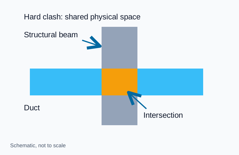
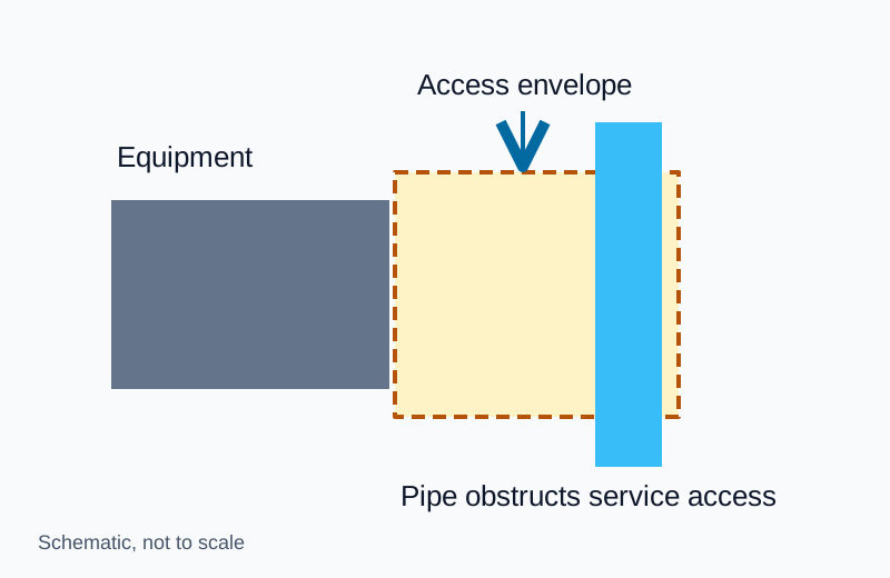
A hard clash is a physical intersection between modelled objects. A clearance conflict occurs when objects remain separate but violate the space needed for insulation, installation, operation or maintenance. Useful MEP coordination finds both, then assigns a decision, updates the responsible model and verifies the revised interface.
Teams often call clearance conflicts “soft clashes.” Use the software’s actual test terminology in the coordination plan. Navisworks uses the Clearance test for distance-based checking; Autodesk also uses “soft clash” for checks involving movement through object animation. Keeping these meanings explicit prevents the wrong test being selected.
Match the test to the question
| Coordination question | Test or model check | Example |
|---|---|---|
| Do physical objects overlap? | Hard intersection | Duct through a structural beam |
| Is the required space preserved? | Clearance or explicit envelope geometry | Pipe in equipment service space |
| Is geometry duplicated? | Duplicate-item check | Repeated export of the same component |
| Can installation happen in sequence? | Time-linked or movement review | Equipment delivery route blocked after enclosure |
Autodesk’s Navisworks 2026 Select tab reference defines Hard, Clearance and Duplicates and explains selection sets. Its test-option guidance makes the software-specific distinction between clearance and animated soft-clash checking.
Establish a trustworthy federation
Agree coordinates, units, model origins, level names and revision identifiers before running tests. Check the discipline exports against known references. A shifted model can produce a convincing but meaningless clash report.
Define the required content for the coordination stage: insulation, fittings, hangers, access panels, equipment removal space, structure, ceilings and openings. Missing geometry is a coverage gap that must be assigned, not accepted as a clash-free condition. Confirm export settings and object classifications with each authoring team.
Build selection or search sets by system, area and object type. A useful test matrix pairs the systems that can meaningfully conflict and records the test type, clearance basis and reviewer. Autodesk notes that hidden objects are excluded from tests; visibility and selected sets therefore belong in the setup check.
Set clearance from the requirement
Service space should come from the equipment documentation and applicable requirements. Insulation thickness comes from the design. Installation space should reflect the approved method and real access constraints. These values can differ within one system, so one blanket distance can either miss important conflicts or create excessive noise.
A hard-clash tolerance filters reported intersections. It does not grant permission to construct an overlap. Likewise, a software default does not establish a legal electrical clearance or manufacturer maintenance envelope. Keep the criterion and its source alongside the test definition.
Resolve MEP routing with an agreed priority
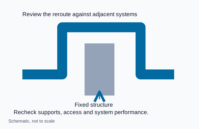
Start with fixed constraints: structure, required headroom, fire-rated assemblies, gravity drainage falls, equipment access and code-required separation. Identify which systems have feasible rerouting options. A gravity pipe’s invert constraints may make it less flexible than a small pressure line, but the proposed resolution still needs discipline review.
Rules of thumb such as “small pipe yields to large duct” can organize discussion. They cannot authorize cutting a beam, reducing a required slope, violating electrical working space or compromising system performance. Pressure, noise, firestopping, supports, drainage and maintenance access all matter after a route changes.
Use sections through congested areas and review the combined envelope. A route that fits in plan may fail at a beam crossing or access panel. Assign openings and sleeves explicitly to the responsible discipline before concrete placement or fabrication.
Close the issue with a verified revision
Each actionable issue needs an identifier, location, affected elements, model versions, viewpoint, responsible owner, required decision and due date. Group multiple clashes caused by one routing problem so the team resolves the underlying conflict rather than counting screenshots.
The buildingSMART BIM Collaboration Format supports exchange of model-related issues and viewpoints across tools. Check the actual software versions and exchange behavior before relying on a project workflow.
After the design decision, update the authoring model, issue the agreed revision and rerun the affected tests. Close the issue against that revision and retain the disposition. A changed status alone cannot demonstrate that the geometry, clearance or construction information changed.
Before releasing fabrication, review outstanding exceptions, model coverage and approved drawings with the responsible designers and trades. Model coordination supports constructability; project approvals and site inspection remain separate responsibilities.
Return to smart jobsite technology for survey controls, GNSS and data-quality checks.
Explore the related topic and technical references.