Concrete Slump Test Procedure, Placement Timing & Field Curing
Field engineering guide to the concrete slump test, composite truck sampling, ready-mix discharge limits, jobsite water addition, and cylinder curing rules.
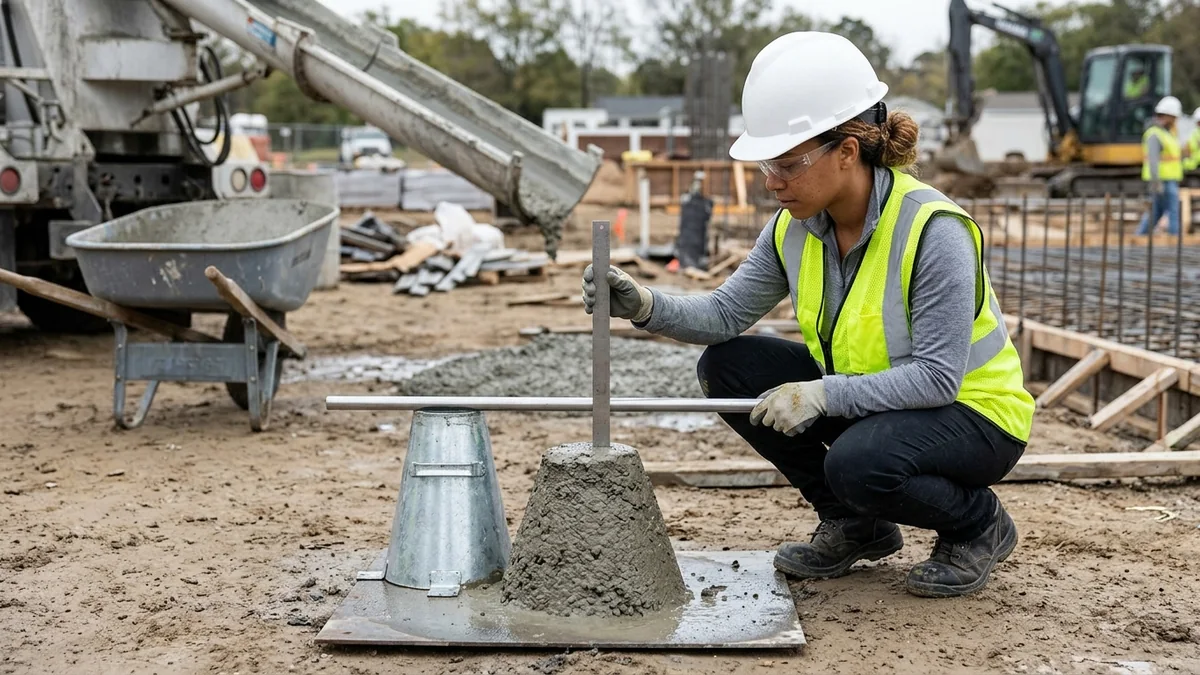
Fresh ready-mix concrete placement requires a field concrete slump test, representative load sampling, discharge tracking, and controlled specimen curing to prevent premature stiffening, cold joints, honeycombing, and load rejection on the jobsite. Slump is measured by ASTM C143, slump flow for self-consolidating concrete is measured by ASTM C1611, and slump loss is the reduction in slump from the time of original batching to the point when concrete is discharged from a truck mixer or other delivery vehicle. Obtain one composite sample for each class of concrete at least once per day, once for each 150 yd3 of concrete, or once for each 5000 ft2 surface area for slabs or walls. Acceptance of concrete shall be based on strength test results of standard cured cylinders in accordance with ASTM C31 and tested at 28 days in accordance with ASTM C39, where strength test results at the designated age shall be the average of two 6 x 12 inch or three 4 x 8 inch specimens. Across modular and prefabricated building systems as well as precast concrete and cast-in-place schedule and dimensional comparisons, field quality personnel use uniform slump verification, batch ticket audits, and cylinder protection to lock in structural performance before forms are filled.
| Field Verification Stage | Governing Control Parameter | Primary Failure Mode Prevented |
|---|---|---|
| Slump Cone Mold Geometry | If formed by the spinning process, there shall be no point on the mold at which the thickness is less than 0.045 in., and the mold shall be in the form of the lateral surface of the frustum of a cone with the base 8 in. in diameter, the top 4 in. in diameter, and the height 12 in. | Non-uniform wall friction and inaccurate vertical subsidence height. |
| Steel Tamping Rod Geometry | The tamping rod has a 16 mm (5/8 in.) diameter and is 400 mm (16 in.) to 600 mm (24 in.) long, with a hemispherical tip the same diameter as the rod. | Aggregate particle crushing, internal voids, or base plate gouging. |
| Vertical Lift and Execution Window | Raise the mold 300 mm (12 in.) in 5 ±2 seconds by a steady upward vertical lift with no lateral or torsional (twisting) motion, and complete the entire operation from the start of filling through removal of the mold without interruption within an elapsed time of 2 1/2 minutes. | Lateral shear distortion and evaporative surface stiffening inside the mold. |
| Composite Sampling and Test Start Window | Obtain the composite sample within 15 minutes from the start of sampling; the minimum size of the sample used for strength tests shall be 28 L (1 ft3), tests for slump, temperature, and air shall start within 5 minutes after obtaining a final portion of the composite sample, and molding specimens shall start within 15 minutes after fabricating the composite sample. | Stale sample hydration drift prior to slump, air, and cylinder molding. |
| Ready-Mix Truck Discharge Window | Discharge of the concrete shall be completed within 1-1/2 h after the introduction of the mixing water to the cement and aggregates or the introduction of the cement to the aggregates, and this time limitation is permitted to be waived by the purchaser if the concrete is of such slump or slump flow after the 1-1/2 h time limit has been reached that it can be placed, without the addition of water, to the batch. | Hydration heat buildup, drum over-mixing, and loss of placement workability. |
| Initial Cylinder Curing Storage | Store standard-cured specimens for a period up to 48 h after molding to maintain the specified temperature and moisture conditions. | Thermal shock, moisture evaporation, and depressed compressive break results. |
Composite Load Sampling and Placement Point Rules Before the Slump Test
Accurate field workability verification starts at the revolving drum chute or pump discharge rather than at the base plate, because non-representative grab samples must not be obtained from the very first or very last portions of a ready-mix load. Before setting up the slump cone on foundation pads verified through soil subgrade compaction and optimum moisture verification, the field technician collects and remixes a composite sample from the middle portion of the batch.
Revolving Drum Truck Mixer Sampling Thresholds and Preliminary Checks
Field technicians distinguish between an early indicator check taken right after initial chute discharge and a full composite acceptance sample drawn from the middle of the load.
Do not obtain samples from the very first or very last portions of the batch (before 10 percent and after 90 percent has been discharged); the size of the sample will be 1.5 times the volume of concrete required for the specified testing, but not less than 0.03 m3 (1 ft3), and all increments must be obtained within 15 min. The sample for air content, slump, and temperature may be taken after at least 1/5 m3 (1/4 yd3) of concrete has been discharged for routine air content and slump tests. Perform sampling by repeatedly passing a receptacle through the entire discharge stream or by completely diverting the discharge into a receptacle, and regulate the rate of discharge of the batch by the rate of revolution of the drum and not by the size of the gate opening. When sampling from revolving drum truck mixers or agitators, obtain the sample after a minimum of 1/2 m3 (1/2 yd3) of concrete has been discharged and after all of the water has been added to the mixer, and do not obtain the sample from the very first or last portions of the batch discharge. If slump is measured prior to discharging concrete on the job, it should be on a preliminary sample obtained after discharging the first 1/4 cu. yd. [0.2 m3] as an indicator of concrete consistency and not an acceptance test, whereas tests for acceptance of concrete should be on samples obtained in accordance with ASTM C172.
Continuous Mixers, Pump Booms, Placement Locations, and Oversize Sieving
When concrete is delivered through continuous mixers, conveyor belts, or articulated pump booms, sampling locations and boom handling directly affect entrained air stability and workability measurements.
When sampling from continuous mixers, after obtaining the composite sample, wait at least 2 min. but not more than 5 min. before beginning tests. When sampling from pump or conveyor placement systems, obtain the sample after a minimum of 1/2 m3 (1/2 yd3) of concrete has been discharged and after all of the pump slurry has been eliminated. When sampling from pump or conveyor placement systems, do not lower the pump arm from the placement position to ground level for ease of sampling, as it may modify the air content of the concrete being sampled. When sampling to determine whether compressive strength conforms to a strength specification, take the sample as close as practicable to the mixer discharge; when sampling to determine compressive strength for form stripping purposes, take the sample as close as practicable to the final resting place of the concrete. Prior to testing or molding test specimens, remix the sample with a shovel to ensure uniformity, protect the sample from sunlight and wind, and ensure combined testing and molding time does not exceed 15 min from the time of sampling. Obtain the sample in accordance with WAQTC TM 2; if the concrete mixture contains aggregate retained on the 37.5 mm (1 1/2 in.) sieve, remove the aggregate by wet sieving over a 37.5 mm (1 1/2 in.) sieve, and begin testing within five minutes of obtaining the sample.
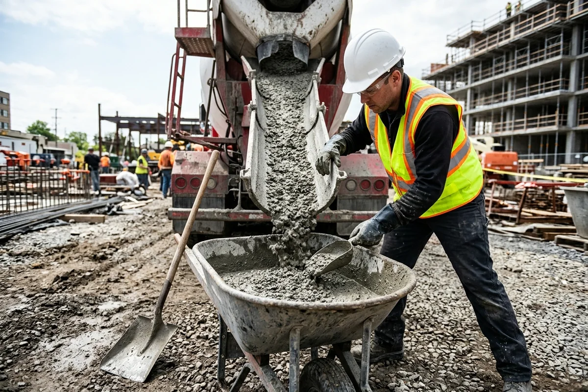
Key Takeaway: Regulate chute flow by drum revolution speed rather than gate opening, collect composite increments from the middle of the batch, never lower a pump boom strictly for ground sampling, and remix the composite sample with a shovel before starting field tests.
Slump Cone Apparatus, Tamping Rod Geometry, and Three-Layer Execution
Field technicians eliminate operator bias during the concrete slump test by inspecting mold rigidity, verifying nonabsorbent base surfaces, and following a disciplined three-layer filling and rodding sequence.
The vertical subsidence equation governing field measurement is Slump Displacement = Initial Mold Height - Displaced Specimen Vertical Center Height, which isolates plastic shear resistance under self-weight.
Mold Dimensional Verification, Measuring Graduation, and Mixture Applicability
Every piece of field apparatus must resist indentation, maintain seamless conical geometry, and operate within plastic and cohesive mixture boundaries.
Individual diameters and heights of the slump mold shall be within 1/8 in. of the prescribed dimensions, and the mold shall be provided with foot pieces and constructed without a seam. The tape measure or ruler used for the slump test has at least 5 mm or 1/8 in. graduations. Concrete having a slump less than 5/8 in. may not be adequately plastic, and concrete having a slump greater than 9 in. may not be adequately cohesive for this test to have significance.
Equal-Volume Layer Filling, Rodding Penetration, and Shear Evaluation
Because the frustum cone tapers toward the top opening, filling by equal third-heights instead of equal third-volumes starves the bottom layer of concrete and skews consolidation density.
Fill the mold 1/3 full by volume to a depth of approximately 67 mm (2 5/8 in.) and consolidate the bottom layer throughout its depth with 25 strokes of the tamping rod using the rounded end. Fill the mold 2/3 full by volume to a depth of approximately 155 mm (6 1/8 in.) and consolidate this layer with 25 strokes of the tamping rod, penetrating approximately 25 mm (1 in.) into the bottom layer. Measure the distance between the bottom of the rod and the displaced original center of the top of the specimen to the nearest 5 mm (1/4 in.); if a decided falling away or shearing off of concrete from one side or portion of the mass occurs, disregard the test and perform a new test on another portion of the sample.

Key Takeaway: Stand firmly on both foot pieces, fill the cone in three equal-volume increments, penetrate slightly into the underlying layer when rodding upper lifts, and disregard any test where one side of the concrete mass shears or slides away.
Slump Tolerances, Preliminary Sample Checks, and Retest Protocol
Interpreting a field slump reading requires distinguishing between project specification bands that set an upper workability ceiling and those that target a center-point nominal slump. When a batch falls outside target workability limits on arrival, project specifications establish strict adjustment and check-testing steps before a load is accepted or refused.
| Specification Structure | Target Workability Condition | Governing Allowance and Retest Rule |
|---|---|---|
| Upper Ceiling Slump Specification | Specified Upper Limit Without Target Center | When slump is specified as a Maximum Slump, the tolerance for under 3 in. (75 mm) is +0 to -1 1/2 in. (40 mm), and for over 3 in. (75 mm) is +0 to -2 1/2 in. (65 mm). |
| Nominal Slump Specification | Specified Center-Point Workability Target | When slump is specified as a Nominal Slump, the tolerance for under 2 in. (50 mm) is ±1/2 in. (15 mm), for 2 - 4 in. (50 - 100 mm) is ±1 in. (25 mm), and for over 4 in. (50 mm) is ±1 1/2 in. (40 mm). |
| Preliminary Sample Evaluation | Low Slump Adjustment vs High Slump Retest | When the slump and air content measured on the preliminary sample are lower than specified, jobsite adjustments with water or admixtures followed by adequate mixing are permitted; if slump and air contents are higher, a retest is made immediately, and if the retest fails, the concrete is considered to have failed the requirements of the specification. |
Once any jobsite water or admixture adjustment is completed and remixed, all strength acceptance specimens must reflect the final placed batch composition.
The concrete used to make the molded specimens shall be sampled after all on-site adjustments have been made to the mixture proportions, including the addition of mix water and admixtures, and this practice is not satisfactory for making specimens from concrete not having measurable slump.
Key Takeaway: Confirm whether project documents specify an upper ceiling or a nominal target slump, allow permitted mixing adjustments when preliminary slump reads low, and execute an immediate retest before rejecting a load that reads high.
Ready-Mix Truck Discharge Time Limits, Drum Revolutions, and Jobsite Water Addition
Tracking concrete truck discharge time and drum revolutions protects cast-in-place and prefabricated structural elements from hydration stiffening, thermal cracking, and unauthorized water-cementitious ratio increases. When unmonitored loads are retempered past design water limits, adding water in excess of the design mixing water reduces strength and increases susceptibility to cracking.
Delivery Time Windows, Drum Revolution Agreements, and Retempering Rules
Extended haul distances, traffic delays, and solar heating accelerate cement hydration and evaporative water loss inside revolving truck drums, reducing slump between batching and discharge. An engineering rule for field placement is that any water introduced at the jobsite requires documented batch-water verification and high-speed drum remixing so the entire load achieves uniform consistency before unloading.
Concrete should achieve the required slump with consideration of the delivery time that can range from 45 to 90 min. Limits on discharge for truck mixer revolutions or time from batching are permitted to be set between the contractor and the concrete producer because project conditions vary considerably, and a default time or revolution limit is not considered to be appropriate or protective to the quality of concrete.
| Jobsite Control Aspect | Operational Rule and Mixing Requirement |
|---|---|
| Water Addition Rule of Thumb | A rule of thumb for jobsite water addition is 1 gallon, or roughly 10 lb., of water per cubic yard for 1 inch increase in slump [5 liters, or 5 kg, of water per cubic meter for 25 mm increase in slump]. |
| Drum Remixing Revolutions | ASTM C94 requires an additional 30 revolutions of the mixer drum at mixing speed after the addition of water, or in some cases 10 revolutions if the truck is able to mix at 20 revolutions per minute (rpm) or faster. |
| Excess Water Quality Liability | Adding water in excess of the design mixing water reduces strength and increases susceptibility to cracking, and if the purchaser requests additional water in excess of the design mixing water, the purchaser assumes responsibility for the resulting concrete quality. |
Key Takeaway: Coordinate delivery time windows with batch plant dispatch, prefer held-back design water for jobsite additions and do not add water if the maximum water-cementitious materials ratio or maximum slump is reached or more than about 1/4 cubic yard (0.2 m3) has been discharged (excess design water only if the purchaser assumes responsibility), and complete full mixing-speed drum revolutions before drawing acceptance samples.
Molding, Initial Curing, and Transporting Concrete Test Cylinders
Strength acceptance cylinders molded alongside the concrete slump test represent the in-place structural concrete only when cast, cured, and transported without moisture loss, temperature extremes, or mechanical jarring. Field curing errors during the initial storage window that are not in accordance with ASTM C31/C31M may cause up to a 20% reduction in the 28-day compressive strength.
Cylinder Mold Selection, Consolidation Methods, and Vibration Frequency
Selecting rigid single-use plastic or steel molds, discarding air-meter concrete, and matching the consolidation method to mixture slump ensures uniform specimen density.
Molds for casting concrete test specimens shall conform to Specification C470/C470M, and cardboard cylinder molds shall not be used for standard-cured specimens. When the nominal maximum size of the coarse aggregate exceeds 50 mm [2 in.], the concrete sample shall be treated by wet sieving through a 50-mm [2-in.] sieve as described in Practice C172/C172M, and for acceptance testing for specified compressive strength, cylinders shall be 150 by 300 mm [6 by 12 in.] or 100 by 200 mm [4 by 8 in.]. Determine and record the air content in accordance with either Test Method C173/C173M or Test Method C231/C231M, and the concrete used in performing the air content test shall not be used in fabricating test specimens. Under Table 3 Method of Consolidation Requirements, concrete with a slump of 25 mm [1 in.] or greater is consolidated by rodding or vibration, and concrete with a slump less than 25 mm [1 in.] is consolidated by vibration. Internal vibrators used for molding specimens shall have a vibrator frequency of at least 150 Hz [9000 vibrations per minute] while operating in the concrete, and the diameter of a round vibrator shall be no more than one-fourth the diameter of the cylinder mold or one-fourth the width of the beam mold. For each upper layer of a rodded specimen, allow the rod to penetrate through the layer being rodded and into the layer below approximately 25 mm [1 in.], and after each layer is rodded, tap the outsides of the mold lightly 10 to 15 times with the mallet to close any holes left by rodding and to release any large air bubbles.
Initial Curing Temperatures, Laboratory Transport, and Strength Loss Prevention
Moving fresh cylinders promptly onto a level curing shelf, maintaining strict temperature bands for conventional and high-strength mixtures, and limiting transport time prevent artificial compressive strength penalties.
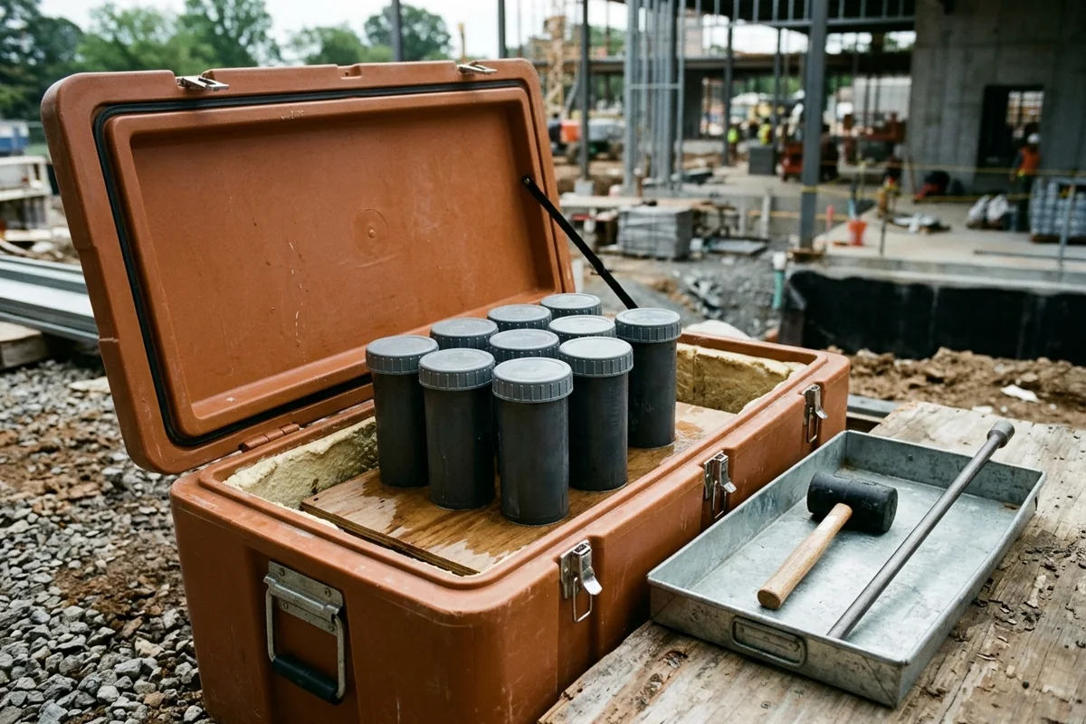
The supporting surface on which specimens are stored shall be level to within 20 mm/m [1/4 in./ft], and if specimens are not molded in the location where they will receive initial curing, ensure that the specimens have been moved to the initial curing location no later than 15 min after molding operations have been completed. For concrete mixtures with a specified strength less than 40 MPa [6000 psi], maintain the initial curing temperature between 16 and 27°C [60 and 80°F]; for concrete mixtures with a specified strength of 40 MPa [6000 psi] or greater, maintain the initial curing temperature between 20 and 26°C [68 and 78°F]. Prevent moisture loss during transportation by wrapping the specimens in plastic or wet burlap, surrounding them with wet sand, or using tight fitting plastic caps on plastic molds, and transportation time shall not exceed 4 h. Upon completion of initial curing and within 30 min after removing the molds, cure cylinder specimens with free water maintained on their surfaces at all times at a temperature of 23.0 ± 2.0°C [73.5 ± 3.5°F] using water storage tanks or moist rooms complying with Specification C511. If initial curing is not in accordance with ASTM C31/C31M, there may be up to a 20% reduction in the 28-day compressive strength. Specimens initially cured in air for 1 day at 37, 73, and 100°F achieved 100%, 92%, and 88%, respectively, of the strength of specimens that were moist cured at 73°F from the time of molding until testing (5590 psi [38.5 MPa]).
Key Takeaway: Never reuse air-meter concrete for strength cylinders, match rodding or internal vibration to the measured slump, maintain tighter curing box temperatures for high-strength mixtures, and transfer capped cylinders to laboratory moist curing within the allowable transport window.
Field Slump and Placement Acceptance Worksheet
Field inspectors and concrete superintendents use the following verification sequence for every ready-mix truck arrival to document sampling, slump execution, discharge timing, and cylinder protection.
| Inspection Phase | Field Verification Action | Pass Criterion | Corrective Action on Deviation |
|---|---|---|---|
| Delivery Ticket Check | Review batch timestamp, mixture identification, revolution counter, and held-back water allowance prior to unloading. | Ticket data complete and truck within allowable haul time and revolution threshold. | Hold chute discharge and consult the project engineer before unloading. |
| Composite Chute Sampling | Divert the full discharge stream into a dampened wheelbarrow at multiple intervals from the middle portion of the load. | Composite sample collected after initial discharge and before final discharge, then remixed. | Discard any grab sample taken from the very first or very last discharge increment. |
| Slump Cone Execution | Dampen the cone and base plate, stand on foot pieces, rod three equal-volume layers, strike off, and lift vertically. | Vertical subsidence exhibits true plastic slump within the project specification band. | Disregard shear collapse and run an immediate check test on another portion of the composite sample. |
| Jobsite Water or Admixture Adjustment | Add permitted held-back water or water-reducing admixture prior to discharge and rotate the drum at mixing speed. | Post-mixing slump check meets target workability without exceeding the design water-cementitious ratio. | Refuse any water addition after more than about 1/4 cubic yard (0.2 m3) of concrete has been discharged, or if the maximum water-cementitious materials ratio or maximum slump is reached, rather than after concrete discharge has started or solely beyond the design water limit. |
| Test Cylinder Molding and Curing | Cast cylinders from the same composite sample and store them to prevent moisture loss (e.g. tight-fitting plastic caps) on a level surface inside the curing box. | Curing box maintains required temperature and moisture protection until laboratory pickup. | Adjust heating, cooling, or shading controls and log thermometer readings. |
Frequently Asked Questions
How is fresh concrete sampled from a revolving drum truck mixer before running a slump test?
Field technicians verify that all mixing water has been introduced and collect multiple increments from the middle portion of the batch discharge rather than the initial or final chute flow. When sampling from a revolving drum truck mixer, ensure that all water has been added, sample the concrete at two or more regularly spaced intervals during discharge of the middle portion of the batch, and repeatedly pass a receptacle through the entire discharge stream or completely divert the discharge stream into a sampling container.
How is the top layer of the slump cone filled and consolidated during field execution?
Technicians heap fresh concrete above the top rim of the mold before rodding and replenish the surcharge immediately if consolidation drops the surface below the rim. Fill the mold to overflowing and consolidate the top layer with 25 strokes of the tamping rod penetrating approximately 25 mm (1 in.) into the second layer; if concrete falls below the top of the mold, stop, add more concrete, and continue rodding for a total of 25 strokes.
What happens if the concrete specimen shears off on consecutive slump tests?
When one side of a concrete frustum slides or shears away on back-to-back trials from the same composite sample, the concrete probably lacks the plasticity and cohesiveness necessary for the slump test to be applicable. If two consecutive tests on a sample of concrete show a falling away or shearing off of a portion of the concrete from the mass of the specimen, the concrete probably lacks the plasticity and cohesiveness necessary for the slump test to be applicable.
When is jobsite water addition prohibited on a ready-mix concrete delivery?
Field personnel must block water additions whenever batch water limits or workability ceilings are already met or once concrete placement from the mixer has progressed beyond the initial indicator volume. Do not add water at the jobsite if the maximum water-cementitious materials ratio is reached, the maximum slump is obtained, or more than about 1/4 cu. yd. (0.2 m3) has been discharged from the mixer.
How much indicated compressive strength is lost from improper initial cylinder curing?
Leaving freshly molded cylinders exposed to extreme field temperatures or moisture evaporation causes substantial artificial strength penalties even when the in-place structural concrete is sound. Non-standard or improper initial curing of test cylinders can result in an artificial reduction in the indicated strength of the concrete ranging from 5 to 30 percent or more.
Sources
- Washington State Department of Transportation — Materials Manual Field Operating Procedures for Slump and Sampling Fresh Concrete
- California Department of Transportation — California Test Methods for Slump and Sampling Fresh Concrete
- American Society for Testing and Materials — Practice for Making and Curing Concrete Test Specimens in the Field
- National Institute for Certification in Engineering Technologies — Performance Examination for Sampling Freshly Mixed Concrete
- Western Alliance for Quality Transportation Construction — Field Operating Procedure for Sampling Freshly Mixed Concrete
- National Ready Mixed Concrete Association — Technical Bulletins on Slump Loss, Jobsite Water Addition, Acceptance Testing, and Cylinder Curing
- American Society of Concrete Contractors — Position Statement on Concrete Discharge Time Requirements
- Virginia Ready-Mixed Concrete Association — Technical Bulletin on Initial Curing of Concrete Test Cylinders
Explore the related topic and technical references.