Retaining wall weep holes: spacing, backfill and hydrostatic relief
Understand wall drainage paths, filtration, collectors and maintainable outlets, plus the project-specific limits of published weep-hole spacing details.
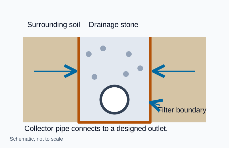
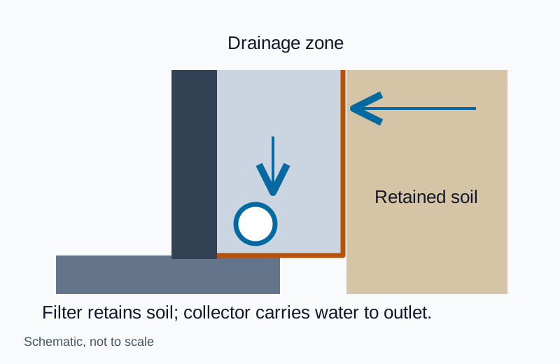
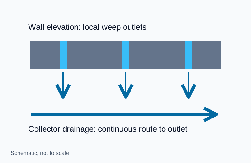
Retaining-wall drainage needs a complete path: water must reach a drainage zone, pass through an appropriate filter, enter a collector or weep, and discharge to a suitable outlet. Weep holes alone cannot compensate for clogged backfill or an outlet below an obstructing grade.
Water retained behind a wall adds lateral pressure. The structural and geotechnical design must establish groundwater assumptions, drainage reliability and the loads used in design. Cracking, displacement or rapid water accumulation calls for professional assessment and control of access around the affected area.
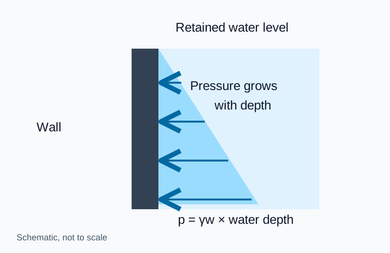
Why water depth changes the load
For water at rest, pressure increases with depth: p = γw × h, where γw is water unit weight and h is depth below the water surface. The pressure diagram is triangular. A higher water level changes both pressure magnitude and the loaded height.
Drainage lowers water accumulation only while the designed flow path remains functional. The Iowa State CTRE report, Design of Maintainable Drains for Earth Retaining Structures examines wall drainage arrangements and maintenance, including clogging concerns. Its laboratory configurations belong to that study’s soil and geometry conditions.
Is there a standard weep-hole spacing?
Spacing comes from the adopted wall detail and drainage design. Wall type, retained height, drainage media, groundwater, outlet elevation and maintenance access all affect the answer.
One specific example is Colorado DOT standard B-601-3. Its drainage annotation calls for 3-inch-diameter drains at a maximum of 24 feet centre to centre, located approximately 3 inches above finished grade, with an exception stated for H ≤ 6 feet. These dimensions belong to that CDOT wall detail and its defined H; use the actual sheet and project plans together.
For another wall type or jurisdiction, obtain the corresponding drainage detail rather than carrying over that spacing. Segmental retaining walls, reinforced-concrete walls, basement walls and masonry cavities have different systems and obligations. A masonry façade weep detail is not a retaining-wall drainage design.
Coordinate the layers behind the wall
| Element | Function | Inspection question |
|---|---|---|
| Surface grading / water diversion | Limit water entering the retained fill | Where does runoff go during and after construction? |
| Drainage aggregate or approved drainage composite | Provide a water path | Is it continuous to the collection point? |
| Filter | Retain surrounding soil | Are compatibility, laps and closures specified? |
| Collector pipe | Convey water along the wall | Are line, fall, access and outlet connected? |
| Weep outlet | Discharge locally where detailed | Can it drain freely and be inspected? |
| Waterproofing, where required | Protect the wall / occupied space | Are continuity and protection maintained? |
Waterproofing and drainage do different jobs. A coating can address water entry through the wall while a drainage system manages water on the retained side. Coordinate protection boards, transitions and penetrations so backfilling does not damage a completed membrane.
Collector pipe and gravel dimensions need a design basis
A four-inch pipe or twelve-inch gravel strip may appear on an individual detail. Its adequacy depends on capacity, material gradation, layout, outlet conditions and the wall system. Specify those dimensions from the approved design alongside the pipe perforation arrangement and filter requirements.
Confirm the discharge location before excavation. Outlets must account for erosion, freezing where relevant, blockage, adjacent property and applicable discharge rules. A collector that ends in retained soil is not a completed drainage route.
Inspect before backfill, then keep access
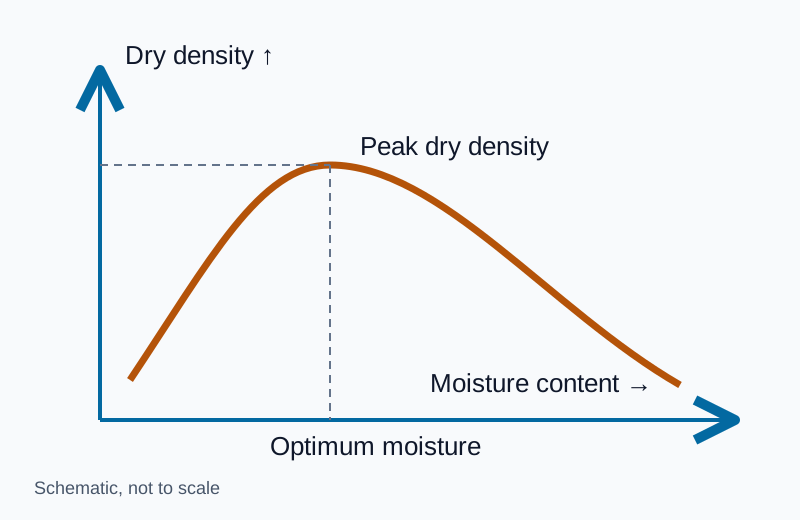
Before concealment, record the filter, drainage medium, pipe connections, outlet elevations and access points. Check that mortar, concrete, soil or construction debris has not blocked an opening. Maintain the specified compaction sequence and equipment setbacks to avoid damaging the drainage system or imposing unapproved construction loads on the wall.
At handover, provide outlet locations and an inspection plan. After heavy rainfall or site changes, look for obstructed outlets, erosion, new seepage, settlement and wall movement. Changes in these conditions warrant investigation. Drilling extra holes through an existing wall can affect reinforcement, waterproofing or stability and requires review by the responsible professional.
Use the geotextile guide to evaluate filter submittals and return to sitework and drainage for earthwork coordination.
Explore the related topic and technical references.