Silt Fence Installation: Trenching Depth, Downslope Posts and J-Hook Returns
Field engineering guide to silt fence installation, 6×6-inch trenching vs. 12-inch static slicing, downslope post spacing, 360-degree roll splices, and J-hook contour layouts.
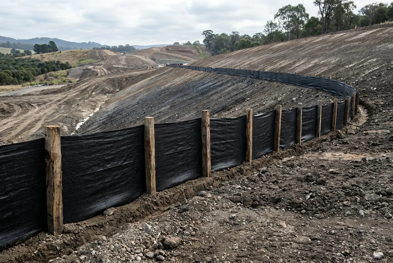
A silt fence retains eroded soil on disturbed slopes only when installed along a constant contour with its bottom geotextile edge keyed into a compacted 6-inch by 6-inch trench (or a 12-inch static-sliced slit), support posts driven on the downslope side, roll joints wrapped 360 degrees around abutting posts, and ends turned upslope into J-hook returns. Laying the bottom fabric edge flat on the ground surface, driving stakes on the upslope water side, or leaving flat unwrapped seams causes undercutting washouts, fastener pull-off failure, and perimeter sediment leaks during the first storm event.
Under ASTM D6462-19 (Standard Practice for Silt Fence Installation and Maintenance) and the U.S. EPA Stormwater Best Management Practice fact sheet (Silt Fences, EPA-832-F-21-028AA), a temporary silt fence functions as a vertical permeable interceptor for overland, non-concentrated sheet flow. Rather than acting as a rapid flow-through sieve, the barrier impounds runoff behind the geotextile to slow transport velocity so suspended soil particles settle out on the upslope side. Coordinating perimeter barriers with overall sitework, earthmoving and drainage control keeps construction sediment out of municipal storm inlets, detention basins, and receiving waters until final stabilization.
| Installation or inspection parameter | Standard engineering requirement | Primary reference basis | Dominant field failure mode if violated |
|---|---|---|---|
| Contributing drainage area | Maximum 0.25 acre (10,890 sq ft) per 100 linear ft of fence (at least 100 linear ft per 10,000 sq ft disturbed) | U.S. EPA EPA-832-F-21-028AA; Iowa SUDAS Section 7E-14; Mile High Flood District (MHFD) Fact Sheet SC-1 | Runoff overtops the fabric crest during moderate rainfall and scours the toe |
| Disturbed slope length & gradient | Maximum 150 ft tributary slope length; slope gradient no steeper than 3:1 (33%) | MHFD Fact Sheet SC-1; Iowa SUDAS Table 7E-14.01 | Sheet flow accelerates into erosive rills and overwhelms single-row storage volume |
| Setback from toe of slope | 6 to 10 ft downslope from the slope toe (or as far as practical) | U.S. EPA EPA-832-F-21-028AA; Iowa SUDAS Section 7E-14 | Inadequate impoundment basin volume; sediment fills the fence prematurely |
| Standard trenching geometry | 6 in. deep × 6 in. wide (15.2 cm × 15.2 cm) trench (4 in. minimum burial in Washington Stormwater Center BMP C233); backfill and compact above grade | U.S. EPA EPA-832-F-21-028AA; Advanced Drainage Systems (ADS) Silt Fence Installation Guide | Runoff pipes beneath unkeyed or loosely backfilled fabric (undercutting washout) |
| Static slicing geometry | 12-in. vertical blade slit with fabric inserted simultaneously; compact with 2 to 4 tractor-wheel passes on both sides | U.S. EPA EPA-832-F-21-028AA (citing ASCE 2001 CERF Report #40565) | Uncompacted slit saturates and washes out under ponded hydrostatic head |
| Support post orientation | Posts driven on the downslope (downstream) side; geotextile fastened to the upslope (upstream) face | Iowa SUDAS Section 7E-14; Washington Stormwater Center BMP C233; ADS Silt Fence Installation Guide | Ponded water and silt load peel staples or plastic ties off upslope posts |
| Post embedment & spacing | 18 to 24 in. embedment (24 in. EPA steel post target; 18 in. min WSC C233, or 12 in. in firm soil); 3–7 ft load-based spacing (6 ft max WSC; 8–10 ft wire-backed DOT T-posts) | U.S. EPA EPA-832-F-21-028AA; Washington Stormwater Center BMP C233 | Posts lean, overturn, or allow fabric top sag and concentrated overflow |
| Top fastener attachment | Steel posts: 3 diagonal plastic ties (≥50-lb test) in the top 8 in. hung on post nipples; Wood posts: heavy staples with wood lath overlay | U.S. EPA EPA-832-F-21-028AA | Lightweight fabric tears at attachment points and slumps between stakes |
| Roll-to-roll post splice | Overlap end post of Roll 1 and start post of Roll 2, wrap fabric 1 full turn (360°) around each post, drive tightly together, wire-tie tops | ADS Silt Fence Installation Guide; state DOT standard details | Unwrapped butt or flat-lap seam pulls open under wet tension, jetting sediment through gap |
| Contour run length & J-hooks | Maximum 200 ft continuous segment; turn 20-ft J-hook upslope at both ends (and every 100 ft along sloped perimeters) | Iowa SUDAS Section 7E-14; U.S. EPA EPA-832-F-21-028AA | Flow concentrates at the lowest contour point or scours gullies around open fence ends |
| J-hook end elevation rule | Ground elevation at bottom of both J-hook ends higher than top of middle fence section | U.S. EPA EPA-832-F-21-028AA (Figures 8 and 9) | Extreme storm runoff bypasses around fence ends instead of spilling over the middle weir |
| Cleanout or replacement trigger | 1/2 fence height (ASTM D6462 / EPA / SUDAS), 1/3 fence height (WSC C233), or 6 in. depth (MHFD SC-1) | U.S. EPA EPA-832-F-21-028AA; Iowa SUDAS Section 7E-14; WSC BMP C233; MHFD SC-1 | Clogged fabric loses storage freeboard; mechanical cleanout tears wet geotextile |
How a Silt Fence Works: Sheet-Flow Ponding vs. Three Field Failure Modes
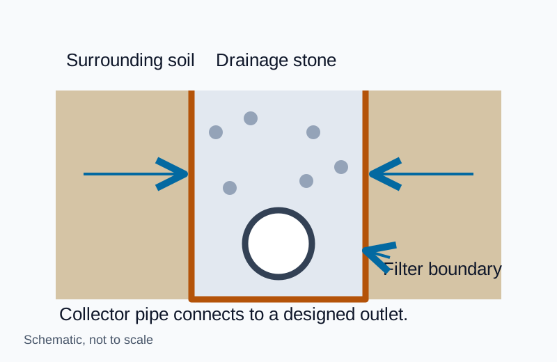
A silt fence captures eroded soil by temporarily impounding overland sheet flow so suspended particles settle out of quiescent water on the upslope side, not by straining high-velocity runoff through geotextile pores. Both Iowa Statewide Urban Design and Specifications (SUDAS Design Manual, Chapter 7, Section 7E-14, Revised 2024/2025 Edition) and ASTM D6462-19 (which is based on AASHTO M288) emphasize this hydraulic boundary: once fine silt particles blind the lower geotextile openings, the fabric acts primarily as a low-head detention weir. That function differs fundamentally from subsurface aggregate filters covered in our woven vs. nonwoven drainage geotextile guide, where needlepunched nonwoven fabrics must maintain high cross-plane permittivity inside a buried French drain trench.
Because a silt fence relies on temporary ponding, it must never be placed across concentrated flow channels, creeks, ditches, or culvert outlets. Iowa SUDAS Section 7E-14 restricts swale or ditch-check installations to minor drainage ways where the 2-year peak discharge is verified at 1 cubic foot per second (1 cfs) or less; flows above 1 cfs require rock check dams, manufactured ditch checks, or engineered sediment traps.
Rule-of-Thumb (Tributary Drainage Area & Linear Footage Gate): If a disturbed slope discharges overland sheet flow to a perimeter boundary, limit the contributing area to 0.25 acre (10,890 sq ft) per 100 linear feet of silt fence—or provide at least 100 linear feet of silt fence per 10,000 sq ft of disturbed ground per U.S. EPA BMP guidance—and subdivide runs where disturbed slope length exceeds 150 feet or slope gradient reaches 3:1 (33%).
To size the minimum total silt fence length ($L_{\text{min}}$, in linear feet) and minimum segmented contour runs ($N_{\text{runs}}$) before grading begins, apply the EPA tributary area ratio and the Iowa SUDAS 200-foot maximum segment rule:
$$L_{\text{min}} = \left(\frac{A_{\text{disturbed}}}{10{,}000\text{ sq ft}}\right) \times 100\text{ ft}, \qquad N_{\text{runs}} = \left\lceil \frac{L_{\text{min}}}{L_{\text{max_segment}}} \right\rceil$$
- Example calculation (assuming a disturbed grading pad of $A_{\text{disturbed}} = 35{,}000\text{ sq ft}$ and a maximum continuous segment length of $L_{\text{max_segment}} = 200\text{ ft}$): $L_{\text{min}} = (35{,}000 \div 10{,}000) \times 100 = 350\text{ linear ft}$ of silt fence, requiring $N_{\text{runs}} = \lceil 350 \div 200 \rceil = 2$ independent contour segments with 20-foot upslope J-hook returns rather than one continuous perimeter line.
When a silt fence fails during a storm, field inspectors look for three recurring installation defects:
| Field failure symptom | Mechanical root cause | Immediate field remediation |
|---|---|---|
| Bottom washout and piping tunnels under the fabric | Bottom geotextile edge was laid flat on the ground surface weighted with loose stones, or trench backfill was left uncompacted around chain-trencher turns | Re-excavate a 6×6 in. trench (or slice a 12-in. slit), key the fabric flap across the trench bottom and upslope wall, and compact backfill in lifts until it passes the hand-pull test |
| Fabric peeled off posts or posts leaning downslope | Support posts were driven on the upslope (water) side so hydrostatic pressure pulled staples/ties off the posts, or posts were embedded less than 18–24 in. | Drive replacement posts 18–24 in. deep on the downslope side of the fabric, fasten fabric to the upslope post face, and reduce post spacing to 3–5 ft in high-load zones |
| Concentrated mud plumes at roll joints or fence ends | Adjoining fabric rolls were butt-joined or flat-lapped without wrapping posts, or fence ends terminated flat along the slope without upslope J-hooks | Re-splice rolls by wrapping both ends 360° around abutting posts driven tightly together and wire-tied at top; extend 20-ft J-hooks upslope so end ground elevation exceeds middle fence top |
Note that the U.S. EPA silt fence fact sheet illustrates one specialized hard-surface stockpile exception: when protecting a rock and soil stockpile where falling boulders would crush stakes or where precast concrete highway barriers are required along a roadway, crews rest precast concrete barriers directly on a 10-inch bottom apron of filter fabric or weight the fabric base against the concrete barrier toe with stone. On earthen construction perimeters, however, weighing surface-laid fabric with loose rocks does not seal soil pore pathways and rapidly undercuts under ponded head.
Silt Fence Trenching Depth (6×6 in.) vs. Static Slicing (12-in. Slit) and Compaction
Keying the bottom edge of the geotextile below grade and compacting the surrounding soil is the single most important defense against undercutting. Standard civil specifications—including U.S. EPA EPA-832-F-21-028AA and the Advanced Drainage Systems (ADS) Silt Fence Installation Guide—require a 6-inch-deep by 6-inch-wide (15.2 cm × 15.2 cm) anchor trench, while some state manuals such as Washington Stormwater Center Construction BMP Guide C233 permit a 4-inch minimum burial depth when backfilled and tamped firm.
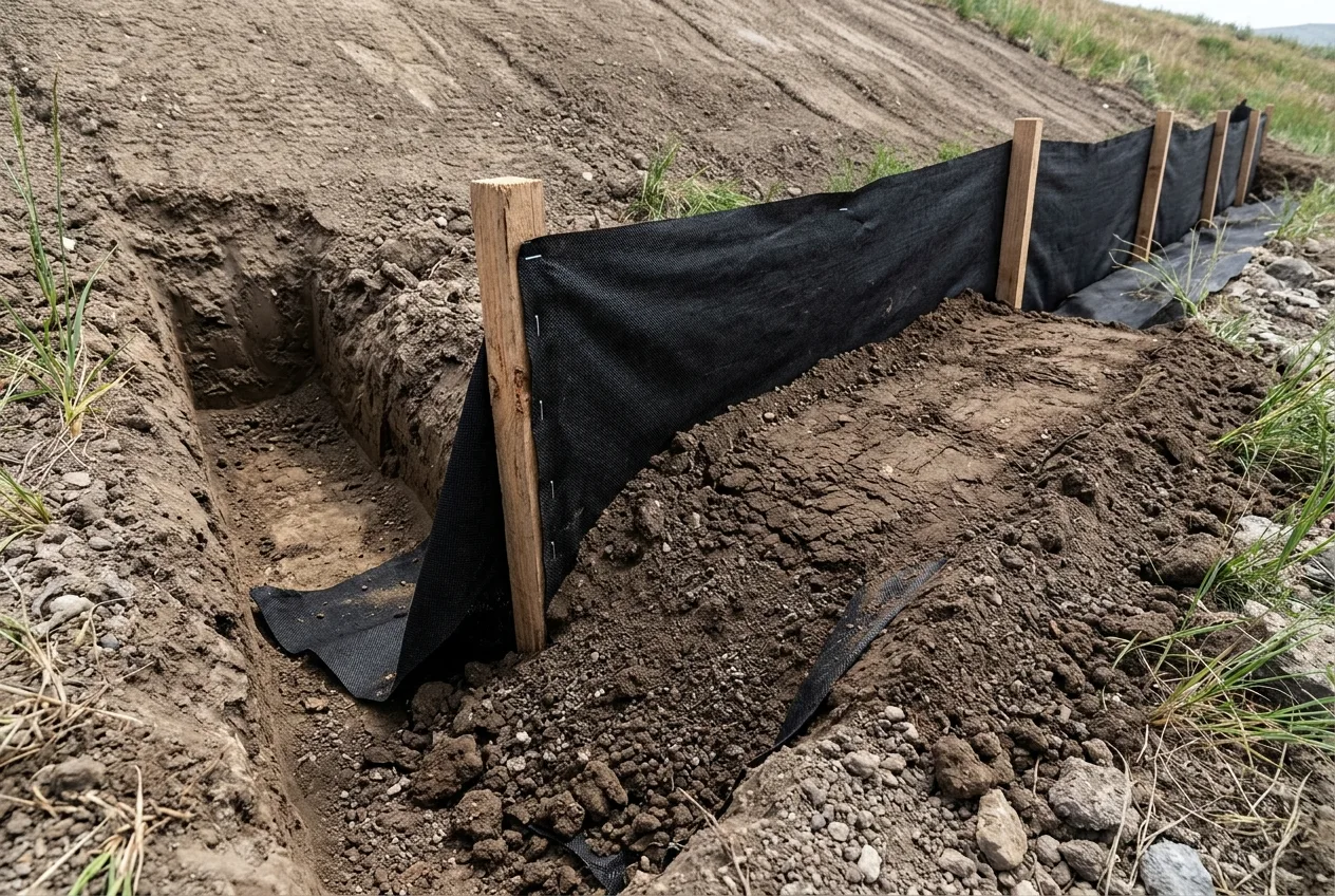
Standard 6×6-inch trenching and why chain trenchers fail at turns
In the conventional trenching sequence, the crew excavates a 6-inch by 6-inch trench along the surveyed contour line, drives support posts on the downslope edge, lays the bottom flap of geotextile into the trench across the bottom and upslope trench wall (leaving roughly 24 to 30 inches of fabric extending above grade), returns excavated soil into the trench, and tamps it until the compacted soil surface sits slightly higher than original grade.
Despite its widespread use, U.S. EPA stormwater guidance documents three mechanical weaknesses of rotary chain trenchers:
- Curved trench walls and turn widening: Chain trenchers cut rounded walls rather than crisp vertical faces, and whenever the operator turns the machine to follow terrain contours, clear utility obstacles, or form an upslope J-hook, the boom cuts a significantly wider excavation (EPA Figure 15).
- Obstructed backfill compaction: Setting posts and draping fabric before compacting the trench makes it difficult for crews to compact soil tightly against both sides of the buried geotextile.
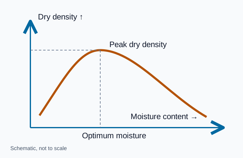
- Subsurface piping washouts: Uncompacted trench backfill retains interconnected air voids. As explained in our Proctor soil compaction guide, loose soil with high void ratios saturates rapidly when water ponds behind the fence, allowing seepage to pipe beneath the buried flap and blow out the retained sediment wedge (EPA Figure 16).
Static slicing (12-inch slit) and tractor-wheel vertical compaction
To eliminate loose trench backfill, the static slicing method pulls a narrow, non-rotating steel blade through the soil to cut a 12-inch-deep vertical slit while simultaneously feeding the bottom edge of the silt fence fabric into the slit directly behind the blade. The slicing blade is contoured to heave the soil slightly upward along the slit edges while minimizing horizontal smearing, creating an ideal geometry for vertical wheel compaction.
Immediately after the blade inserts the fabric, the operator rolls a tractor wheel 2 to 4 passes along both sides of the slit (EPA Figures 12–14). This vertical tire loading compresses soil air voids to achieve an in-place density nearly equal to or greater than the undisturbed native ground, sealing the subsurface interface against infiltration before posts are driven and fastened.
In an EPA-supported independent technology evaluation conducted by the American Society of Civil Engineers (ASCE 2001, Environmental Technology Verification Report for Installation of Silt Fence Using the Tommy Static Slicing Method, CERF Report #40565), static slicing outperformed the two lower performance tiers of trenching and matched or exceeded the highest trenching tier—while the best trenching method required nearly triple the installation time and labor effort to achieve comparable containment.
Rule-of-Thumb (Subgrade Key-In Acceptance Gate): Regardless of whether a run is installed via a 6×6-inch compacted trench or a 12-inch static-sliced slit with 2 to 4 tractor-wheel passes, Mile High Flood District (Fact Sheet SC-1) defines the field acceptance test: the buried geotextile must not pull out when tugged firmly by hand, and zero daylight or air gaps may exist between the ground surface and the fabric base. When ground frost prevents trenching or slicing to depth, Iowa SUDAS Section 7E-14 specifies surface-mounted perimeter controls such as compost filter socks, straw wattles, or wood excelsior logs until the ground thaws.
Downslope Post Placement, Embedment Depth, Spacing, and Fasteners
Support posts must always be installed on the downslope (downstream) side of the trench or slice, with the geotextile fastened to the upslope (upstream) face of the posts. When stormwater and settled silt accumulate behind the fence, hydrostatic force presses the fabric directly against the structural face of the posts. Driving posts on the upslope side reverses the load path: ponded water pushes the fabric away from the posts, transferring the full tensile load onto individual staples or plastic ties until the fabric rips free.
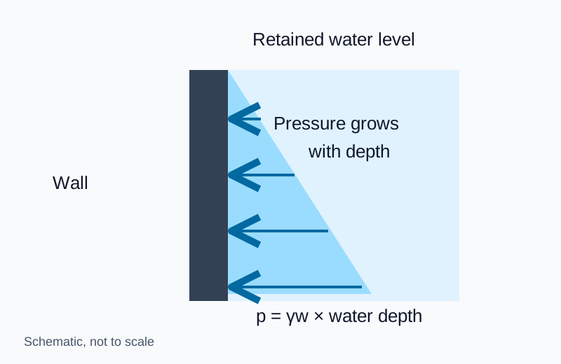
As detailed in our retaining wall hydrostatic pressure guide, lateral water pressure at rest increases linearly with ponded depth ($h$):
$$p = \gamma_w \times h, \qquad F_w = \frac{1}{2},\gamma_w,h^2$$
where $\gamma_w = 62.4\text{ lbf/ft}^3$ is the unit weight of water (rising to $85\text{–}100\text{ lbf/ft}^3$ for saturated fluid silt), $h$ is the ponded depth in feet, and $F_w$ is the resultant horizontal hydrostatic force per linear foot of fence.
- Example calculation (assuming $h = 2.0\text{ ft}$ of ponded stormwater per the U.S. EPA 24-inch design head and a 5-foot post spacing): Clear water alone exerts a base pressure of $p = 62.4 \times 2.0 = 124.8\text{ lbf/ft}^2$ and a horizontal force of $F_w = 0.5 \times 62.4 \times (2.0)^2 = 124.8\text{ lbf per linear foot}$—delivering 624 lbf of horizontal overturning load per post at 5-foot spacing before accounting for denser submerged sediment.
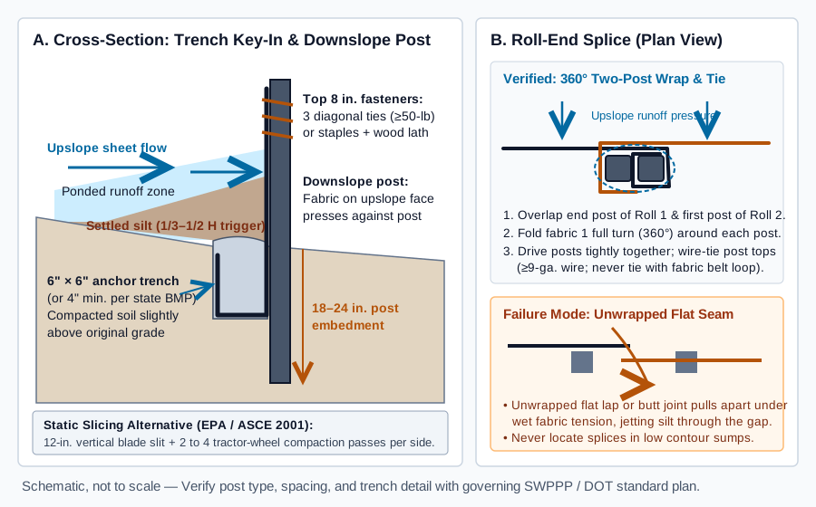
Post material, embedment depth, and spacing across governing manuals
Because post overturning resistance depends on soil stiffness and embedment depth, federal and state manuals scale post spacing and drive depth to the expected hydraulic load:
| Standard / agency manual | Post material & minimum section | Minimum post embedment depth | Maximum post spacing by load condition | Required top fastener detail |
|---|---|---|---|---|
U.S. EPA (EPA-832-F-21-028AA) | Steel posts preferred for compacted soil; 2×2 in. hardwood posts allowed where driveable | 24 in. (2 ft) into compacted soil (to hold 24 in. of water and sediment) | 3–4 ft where water may overtop; 5 ft in most areas; 6–7 ft under low horizontal load | Steel: 3 diagonal plastic ties (50-lb test) in top 8 in. hung on post nipples; Wood: multiple staples + wood lath overlay |
Washington Stormwater Center (BMP C233) | Wood (2×2 in. min) or steel (No. 6 rebar min); add mesh in high-wind zones | 18 in. minimum (12 in. minimum allowed only if soft subgrade is absent); brace/guy if depth cannot be met | 6 ft maximum center-to-center | Fasten on upslope side with staples, wire, or manufacturer-approved clips |
| Standard DOT & supplier practice | 2×2 in. hardwood stakes (standard fence) or steel T-posts (~1.25–1.33 lb/ft) with wire backing | 12 to 18 in. into firm ground (or per state DOT standard drawing) | 6 to 8 ft for unreinforced fabric; 8 to 10 ft (~11 posts per 100-ft roll) for wire-backed steel T-post fence | At least 4 heavy staples per wood stake, or steel wire ties / clips on T-posts |
U.S. EPA field guidance notes a practical constructability constraint with wooden stakes: while 2-inch by 2-inch hardwood posts have sufficient bending strength, crews frequently cannot drive them more than 6 to 8 inches into dry, compacted subgrade without splitting the wood top. Steel T-posts or U-posts can be driven the full 24 inches into dense soil with a post driver and extracted for reuse at final stabilization.
When fastening geotextile to steel posts without wire mesh backing, the EPA specifies three plastic ties per post (minimum 50-pound tensile test strength) concentrated within the top 8 inches of the fabric, with each tie looped over a post nipple and oriented diagonally so the tie captures both vertical warp and horizontal weft yarns. On wooden stakes, driving staples through a continuous wood lath strip overlaid against the fabric prevents wind flutter and hydrostatic tension from tearing lightweight woven slit-film around the staple crowns.
Joining Rolls: 360-Degree Post Wrap Splices vs. Flat Overlaps
A 100-foot roll of silt fence rarely spans an entire grading perimeter. When crews join two rolls by simply butting the end posts together or overlapping loose fabric between stakes, the first rain event stretches the wet geotextile, pulls the unsealed vertical seam apart, and jets sediment-laden water through the gap (EPA Figure 19).
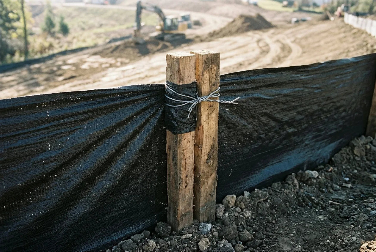
To construct a continuous, sediment-tight splice under the Advanced Drainage Systems (Silt Fence Installation Guide) and DOT field procedures:
- Keep splices out of low contour sumps: Never locate a roll splice at the lowest elevation point along a fence segment where maximum water depth and hydrostatic head concentrate.
- Overlap the terminal posts: Position the last post of the first silt fence roll and the first post of the second roll so the two fabric ends overlap at the post location.
- Wrap each post one full turn (360°): Fold the end of each fabric roll around its respective post at least one full 360-degree revolution (or wrap both overlapping fabric ends together around a shared post where specified by the state DOT detail) so water pressure locks the fabric layers against the post face.
- Drive the wrapped posts tightly together: Drive both wrapped posts side-by-side into the downslope edge of the trench to the full 18-to-24-inch embedment depth, ensuring the bottom fabric flaps are continuously keyed and compacted inside the 6×6-inch trench.
- Bind the post tops with wire or heavy cord: Secure the tops of the two adjoining posts tightly together using 9-gauge or heavier steel tie wire or heavy-duty cord. Where pre-assembled silt fence rolls include stitched fabric belt loops near the top edge, ADS explicitly warns never to use the fabric belt loop itself to tie adjoining post tops together—the belt loop is designed only to twist into a single-post hanger loop before driving a line post, whereas two-post roll splices require rope or wire.
J-Hook Silt Fence Layout, Contour Setbacks, and Slope Spacing
Running a silt fence straight down a slope or installing an unbroken 500-foot perimeter line along a sloping road edge turns the fence into a diversion gutter. Runoff flows parallel to the upslope fabric face, erodes a channel along the trench line, and concentrates at the lowest elevation point—where it rapidly overtops and blows out the fence (U.S. EPA Figure 4).
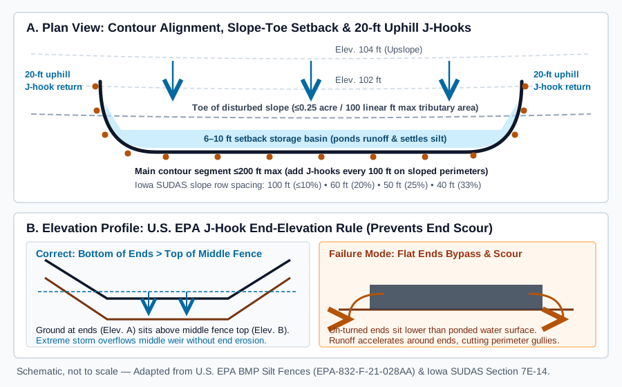
Contour alignment, 6-to-10-foot toe setback, and 20-foot J-hooks
Effective layout geometry follows four rules established by U.S. EPA EPA-832-F-21-028AA, Iowa SUDAS Section 7E-14, and Mile High Flood District Fact Sheet SC-1:
- Follow a constant contour elevation: Stake the main body of each silt fence segment along a single topographic contour so sheet flow arrives perpendicular to the fabric and spreads evenly across the impoundment zone.
- Step back 6 to 10 feet from the toe of the slope: Placing the fence directly against the steep base of a cut or fill slope leaves almost zero wedge volume for water and silt to pond. Offsetting the trench 6 to 10 feet away from the slope toe (or as far as site boundaries allow) creates a flat storage bench that increases settling time and extends cleanout intervals.
- Cap continuous segments at 200 feet and turn 20-foot J-hooks upslope: Iowa SUDAS Section 7E-14 limits any individual silt fence section to 200 feet maximum (many unreinforced DOT specifications limit single runs to 100 feet). At both ends of every segment, turn a 20-foot length of fence uphill (“J-hook”) across the contours so water ponds in a contained pocket rather than escaping around the ends.
- Install intermediate J-hooks every 100 feet on sloped perimeters: When a property boundary or roadway right-of-way forces a perimeter silt fence to run parallel to the slope gradient rather than along a level contour, turn a 20-foot J-hook uphill across the slope every 100 feet (Iowa SUDAS Section 7E-14.B.1.d) or install perpendicular check dams (Washington Stormwater Center
BMP C233). Each J-hook acts as a mini-retention basin that arrests longitudinal flow velocity.
The U.S. EPA J-hook elevation rule
Turning the ends of a fence slightly uphill is not enough if the turned ends terminate on low ground. Under the U.S. EPA elevation rule (EPA Figures 8 and 9), survey or grade-rod checks must confirm that the ground elevation at the bottom of both upturned J-hook ends is higher than the top edge of the middle section of the fence:
$$\text{Elevation}{\text{ground, J-hook ends}} > \text{Elevation}{\text{top of fabric, middle weir}}$$
When an extreme cloudburst exceeds the storage volume of the pocket, this elevation differential forces excess water to spill over the top of the middle geotextile section like a broad-crested weir. Overtopping the middle fabric releases only fine suspended particles near the water surface, whereas allowing runoff to flow around low fence ends scours deep erosion gullies around the perimeter posts.
Multi-row spacing on long disturbed slopes
On long disturbed slopes, a single silt fence at the toe cannot intercept rill formation mid-slope. Install a top-of-slope fence to spread incoming runoff into sheet flow and space intermediate contour rows down the slope according to Iowa SUDAS Table 7E-14.01:
| Disturbed slope ratio (Horizontal : Vertical) | Slope gradient (%) | Maximum contour row spacing interval (ft) |
|---|---|---|
| 10:1 or flatter | ≤ 10% | 100 ft |
| 5:1 | 20% | 60 ft |
| 4:1 | 25% | 50 ft |
| 3:1 | 33% | 40 ft |
Post-Storm Inspection, Cleanout Triggers, and SWPPP Field Checklist
Inspect silt fence runs before the first predicted rainfall, on the weekly or biweekly schedule mandated by the project’s Stormwater Pollution Prevention Plan (SWPPP), and immediately after significant storm events. Walk the entire upslope and downslope face to check for bottom undercutting, slumping or over-spaced posts, torn or UV-brittle geotextile, parallel flow channelization, and sediment depth.
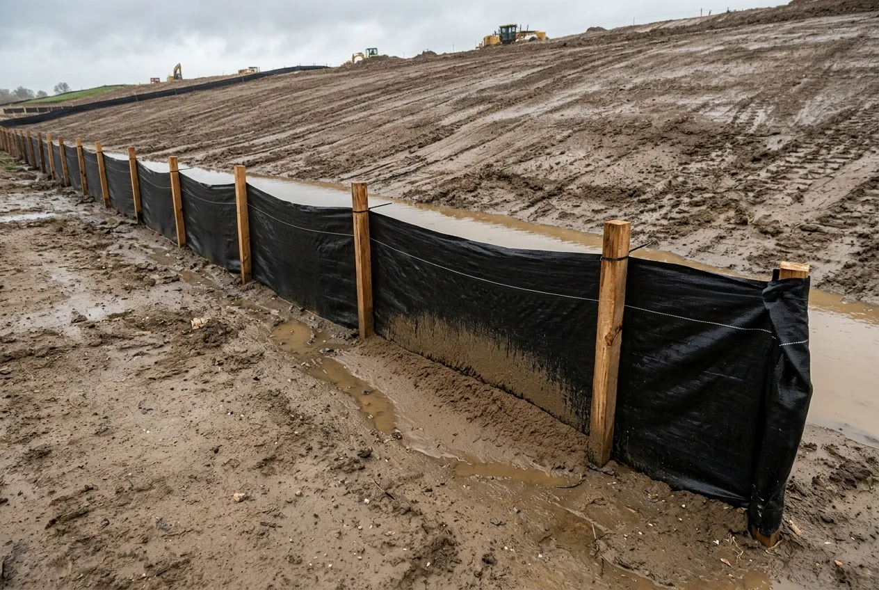
Sediment accumulation triggers and the blinded-fabric replacement decision
Governing stormwater manuals establish clear physical depth triggers for sediment maintenance:
- One-half (1/2) of the fence height: Specified by ASTM D6462, U.S. EPA
EPA-832-F-21-028AA, and Iowa SUDAS Section 7E-14 (for a 24-inch or 18-inch effective fence height, 9 to 12 inches of accumulated silt). - One-third (1/3) of the fence height: Specified by Washington Stormwater Center BMP C233.
- 6 inches of sediment depth: Specified by Mile High Flood District Fact Sheet SC-1 to preserve impoundment capacity ahead of flash-flood storms.
Rule-of-Thumb (Cleanout vs. Parallel Replacement Fence): When accumulated sediment reaches 1/3 to 1/2 of the fence height and the geotextile pores are blinded with fine clay or silt, leave the trapped sediment and existing fence in place and install a new parallel silt fence upslope or downslope whenever site space allows (U.S. EPA Figure 23; Iowa SUDAS Section 7E-14.D).
Both the U.S. EPA and Iowa SUDAS highlight why mechanical backhoe cleanout frequently fails in the field:
- Once fine particles clog the woven openings, scraping soil away from the upslope face does not unclog the fabric—leaving a non-draining barrier with minimal storage capacity.
- Retained soil behind a silt fence stays saturated and soft after storms, making heavy equipment access difficult and causing excavator buckets to snag, tear, or unkey the buried geotextile flap.
- Only where tight property lines prohibit a second parallel fence should crews excavate trapped silt by hand or carefully controlled equipment, immediately spreading and stabilizing the removed soil upslope and replacing any torn fabric sections.
Final stabilization and barrier removal
A silt fence is strictly a temporary construction control. Keep all segments maintained until land-disturbing work finishes and the contributing upslope area achieves permanent stabilization—such as the 70% vegetative cover threshold cited in the U.S. EPA lakeshore restoration benchmark or the final cover density required by the state NPDES permit. At final removal, pull out the posts (reusing intact steel posts and undamaged stakes), dispose of degraded geotextile fabric, spread the trapped topsoil evenly across the disturbed area, and seed and mulch the trench scar.
SWPPP Silt Fence Trench, Post, Splice & J-Hook Field Inspection Checklist
Use the field verification table below during pre-storm installation sign-off and post-precipitation SWPPP walks:
| Inspection zone | Field verification check | Acceptance threshold / pass criterion | Corrective action if deficient |
|---|---|---|---|
| 1. Contour & Tributary Area | Verify main fence run follows a constant contour and check upslope drainage area | ≤ 0.25 acre per 100 linear ft (≥ 100 ft fence per 10,000 sq ft); slope length ≤ 150 ft, gradient ≤ 3:1; no concentrated flow > 1 cfs | Subdivide drainage area with intermediate contour rows (40–100 ft spacing per SUDAS Table 7E-14.01) or install rock check dams in swales |
| 2. Slope-Toe Setback | Measure horizontal offset between the base of the disturbed slope and the trench line | 6 to 10 ft setback from slope toe (or maximum practical distance) to provide storage volume | Relocate new or replacement fence line further downslope from the toe to create an adequate settling basin |
| 3. Trench / Slice & Compaction | Perform hand-pull test on bottom fabric edge and inspect ground-to-fabric interface | 6×6 in. trench (or 4 in. state min) backfilled above grade, or 12-in. static slice with 2–4 wheel passes; cannot be pulled out by hand; zero ground gaps | Re-excavate undercut zones, re-key bottom fabric flap across trench floor and upslope wall, and mechanically tamp backfill in lifts |
| 4. Post Side, Depth & Spacing | Check post position relative to fabric, measure exposed height vs. driven depth, and check spacing | Posts on downslope side, fabric on upslope face; driven 18–24 in. deep; spaced 3–4 ft (overtopping/low points), 5–6 ft (standard), or 8–10 ft (wire-backed DOT) | Drive supplemental downslope posts at sagging spans; re-fasten any upslope-staked sections to the upslope face of downslope posts |
| 5. Top Fasteners | Inspect top 8 inches of fabric attachment at every steel or wood post | Steel: 3 diagonal plastic ties (≥ 50-lb test) in top 8 in. on post nipples (or wire clips); Wood: heavy staples through wood lath overlay | Replace broken ties or pulled staples immediately; add wood lath strips where wind or water load tears staple holes |
| 6. Roll-to-Roll Splices | Inspect every joint where two rolls of geotextile meet | End posts overlapped, fabric wrapped 1 full turn (360°) around each post, posts driven tightly together, tops bound with ≥ 9-ga. wire; no splices in low sumps | Undo flat-lapped or gaping butt seams; wrap fabric 360° around abutting posts, drive posts flush together, and wire-tie post tops |
| 7. J-Hook Returns & Elevation | Check segment length, uphill end turns, and end ground elevation vs. middle fence crest | Segment ≤ 200 ft; 20-ft J-hooks turned uphill at ends and every 100 ft on sloped perimeters; ground at J-hook ends higher than top of middle fence | Extend J-hooks upslope across contours until ground elevation at the terminal post exceeds the top of the middle weir section |
| 8. Post-Storm Silt & Fabric | Measure accumulated silt wedge height and check fabric for blinding, tears, or UV decay | Silt depth below 1/3 to 1/2 fence height (or < 6 in. per MHFD); no parallel erosion channels or torn panels | Install a second parallel silt fence upslope or downslope of blinded/full runs (or carefully remove and stabilize silt where space is tight) |
Frequently Asked Questions
How deep should a silt fence trench be?
Standard civil engineering specifications—including U.S. EPA EPA-832-F-21-028AA and the ADS Silt Fence Installation Guide—require excavating a 6-inch-deep by 6-inch-wide (15.2 cm × 15.2 cm) trench, laying the bottom geotextile flap across the trench bottom and upslope wall, and compacting backfill slightly above original grade. Some state stormwater manuals (such as Washington Stormwater Center BMP C233) allow a 4-inch minimum burial depth, while machine static slicing inserts the fabric into a 12-inch-deep vertical slit compacted with 2 to 4 tractor-wheel passes on both sides. In all cases, the buried edge must pass the MHFD field check: zero gaps between ground and fabric, and firm resistance when pulled by hand.
Which side of the silt fence do the posts go on?
Support posts always go on the downslope (downstream) side of the trench, and the geotextile fabric is fastened to the upslope (upstream) face of the posts facing the oncoming runoff. That orientation ensures ponded water and accumulated sediment press the fabric against the posts rather than pulling staples, wire clips, or plastic ties off the stakes.
How do you join two rolls of silt fence without leaking sediment?
Never butt two rolls together or flat-lap fabric across an open span between posts. Position the last post of the first roll and the first post of the second roll to overlap, fold the fabric at least one full turn (360 degrees) around each post, drive both wrapped posts tightly together on the downslope side of the trench, and tie the tops of the adjoining posts together with 9-gauge wire or heavy cord (never use the stitched fabric belt loop itself to tie adjoining post tops). Locate all splices away from low contour sumps.
Why do silt fence ends need J-hooks and how long should they be?
Without upturned ends, water impounded behind a silt fence flows laterally along the fabric and escapes around the open ends, scouring perimeter erosion gullies. Turning a 20-foot segment uphill (“J-hook”) at both ends of a contour run—and every 100 feet along a sloped perimeter fence per Iowa SUDAS Section 7E-14—contains runoff in discrete settling pockets. Under the U.S. EPA elevation rule, the ground elevation at the bottom of both J-hook ends must be higher than the top of the middle fence section so extreme storms overflow the middle weir rather than washing out the ends.
For subsurface trench filtration, aggregate wrapping, and AASHTO M288 geotextile survivability classes, continue to our woven vs. nonwoven drainage geotextile guide. To verify soil density and moisture control in structural and trench backfill lifts, see the Proctor compaction test guide or return to the Sitework, Earthmoving & Drainage hub.
Explore the related topic and technical references.