Subsurface Utility Engineering: SUE Levels
How subsurface utility engineering uses ASCE/UESI/CI 38-22 quality levels from records to vacuum excavation, plus design duties and provider criteria.
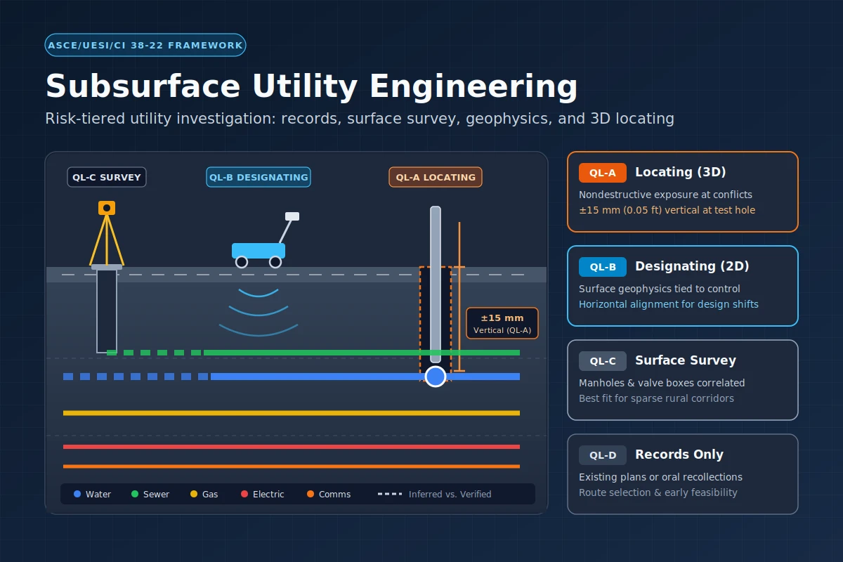
Subsurface utility engineering (SUE) is an engineering practice combining civil engineering, surveying, and geophysics to manage underground utility risks before excavation. Rather than relying on unverified archive drawings, project owners specify four progressive SUE quality levels—from existing records (QL-D) and surface-feature surveys (QL-C) to geophysical designating (QL-B) and nondestructive vacuum excavation locating (QL-A)—matching data accuracy to conflict risk.
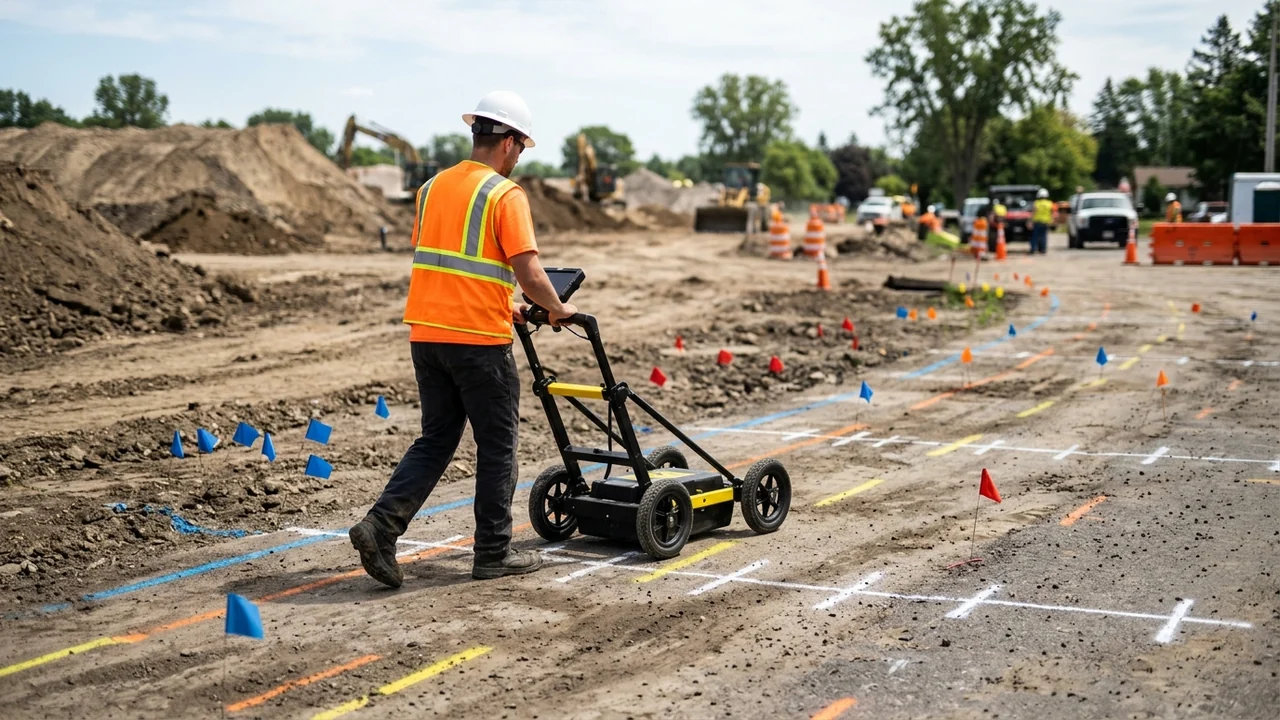
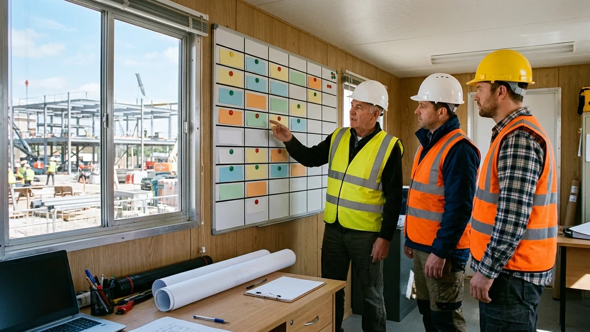
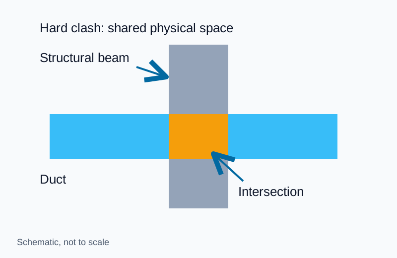
Coordinate subsurface utility investigations inside the broader smart jobsite and survey technology workflow and tie confirmed alignments into corridor sitework, earthmoving, and drainage planning. For radar depth limits and soil conductivity constraints during geophysical passes, review the GPR utility locating guide. Interior model clearances belong to BIM clash detection and MEP coordination, while blade calibration belongs to machine control grading checks.
What is subsurface utility engineering and how does it manage utility risk?
Subsurface utility engineering manages underground utility risks as a structured engineering process rather than a single locating instrument. Published in 2022, ASCE/UESI/CI 38-22 establishes SUE as a branch of engineering practice covering utility mapping at defined quality levels, utility coordination, relocation design, condition assessment, data communication, relocation cost estimating, accommodation policies, and utility design (FHWA SUE Program Overview).
Alongside ASCE/UESI/CI 38-22 (Standard Guideline for Investigating and Documenting Existing Utilities), the American Society of Civil Engineers maintains ASCE/UESI/CI 75-22 (Standard Guideline for Recording and Exchanging Utility Infrastructure Data) to standardize how mapped utility attributes travel across project stakeholders (FHWA Every Day Counts EDC-8 SUE). Since 1991, the Federal Highway Administration has encouraged SUE as an integral part of preliminary engineering on Federal-aid and Federal Lands Highway projects, with SUE service costs eligible for Federal participation.
Why legacy utility records fail before construction
Standard design plans historically relied on owner records paired with broad disclaimers shifting verification risk onto the contractor. As documented in the FHWA Purdue University SUE study, archive utility records routinely prove incomplete or inaccurate for four structural reasons:
- Design drawings are not as-builts: Original plans frequently fail to reflect field-run installations where no record of actual placement was ever made.
- No composite record exists: Decades of separate utility owners, architects, engineers, and contractors burying facilities rarely consolidate drawings into a single master file, and older records are often lost.
- Physical references disappear: Legacy ties measured from a demolished building or the former edge of a two-lane road that later became four lanes or a parking lot lose their geometric datum.
- Abandoned removals linger on sheets: Pipes, lines, and tanks physically removed from the ground often remain drawn on active record maps.
Quantified risk reduction across transportation projects
Providing reliable utility locations early in project development allows designers to shift proposed alignments around existing lines, avoiding unnecessary utility relocations and construction delays. Fewer unexpected utility encounters directly reduce mid-construction redesign delays, utility-strike interruptions, and contractor delay claims while enhancing worker safety against personal injury, property damage, and environmental product releases.
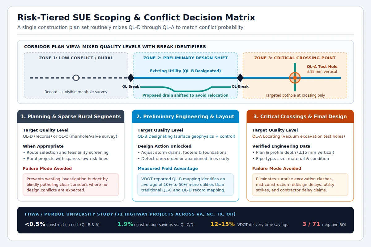
Empirical highway program data confirms these risk reductions across urban, suburban, and rural road classes. In the FHWA-commissioned Purdue University evaluation of 71 highway projects across Virginia, North Carolina, Texas, and Ohio, acquiring QL-B and QL-A data accounted for less than 0.5 percent of total construction costs and produced a 1.9 percent construction cost savings over traditional QL-C and QL-D records, with only 3 of the 71 studied projects showing a negative return on investment. Virginia DOT additionally estimated project delivery time savings of 12 percent to 15 percent from its systemic SUE program, while experienced state transportation agencies—including Georgia, Texas, and Colorado—report better-informed designs, fewer utility-related change orders, improved damage prevention, and fewer surprise utility discoveries during construction.
How are subsurface utility engineering quality levels defined?
Four recognized quality levels classify underground utility information from Quality Level D (the lowest accuracy and highest uncertainty) to Quality Level A (the highest accuracy). Project teams rarely require QL-A along every foot of a corridor; instead, they reserve the highest accuracy for likely conflict points and apply lower tiers where fewer or no conflicts are expected.
| Quality Level | Core field method | Position & attribute certainty | Primary project application | Key engineering boundary |
|---|---|---|---|---|
| Quality Level D (QL-D) | Existing utility records or verbal recollections | Lowest accuracy; rough congestion overview only | Early project planning and corridor route selection | Often incomplete or inaccurate; non-ASCE consultant utility linework defaults to QL-D |
| Quality Level C (QL-C) | Surveyed visible appurtenances (manholes, valve boxes) correlated with QL-D records | Surface features tied to survey; buried runs remain inferred | Rural projects where utilities are sparse or low-consequence to repair or relocate | Omitted or erroneously plotted underground segments remain common |
| Quality Level B (QL-B) | Appropriate surface geophysical methods (designating) surveyed to project control | Existence and approximate horizontal position reproducible by surface geophysics | Preliminary engineering layout of storm drains, footers, and foundations | Horizontal plan alignment only; does not establish verified vertical elevation |
| Quality Level A (QL-A) | Nondestructive exposure (typically vacuum excavation) and direct measurement (locating) | Precise 3D plan and profile typically accurate to 15 mm (0.05 ft) vertical plus type, size, material, and condition | Final design verification at critical crossings and tight vertical clearances | Applies strictly at the exposed test hole rather than unexposed pipe between potholes |
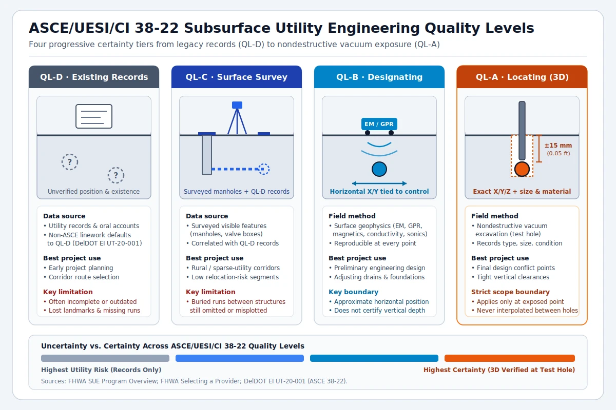
Strict depiction rules prevent low-confidence records from masquerading as certified survey data on contract drawings. Under Delaware DOT Engineering Instruction EI UT-20-001, which aligns plan-set presentation with ASCE 38-22, all existing subsurface utility lines—including traffic signalization, intelligent transportation, and traffic lighting conduits—must display their quality level, and any utility linework not delivered by a SUE consultant under ASCE standards must be depicted as QL-D. Equally important, QL-A certification applies strictly at the specific test hole or fully exposed utility section rather than across unexposed pipe lengths between potholes.
What does Quality Level B designating involve on a project?
Quality Level B designating applies appropriate surface geophysical methods to establish the existence and approximate horizontal position of utilities within project limits, then surveys those positions to project control. By physically sensing buried facilities from the ground surface, QL-B resolves inaccurate archive records, detects abandoned or unrecorded lines, and recovers alignments whose historical surface references have disappeared.
Surface geophysical techniques and reproducibility
Proper technique selection is essential because no single geophysical instrument detects every buried pipe material or soil profile. FHWA provider guidance identifies a multi-instrument designating toolkit spanning extremely low frequency (ELF), very low frequency (VLF), and low frequency (LF) electromagnetic locators, magnetometers, terrain conductivity meters, and resonant sonics alongside complementary radar sweeps (FHWA Selecting a Provider). Under both Purdue study criteria and DelDOT EI UT-20-001, QL-B depictions should be reproducible by surface geophysics at every point shown on the plan documents and surveyed to project-defined horizontal tolerances.
Avoiding design conflicts without over-potholing clear corridors
QL-B designating directly supports preliminary engineering layout decisions. When designers know the horizontal corridor occupied by existing utilities early in design, slight adjustments to storm drainage systems, footers, foundations, and structural alignments can avoid conflicts outright and eliminate expensive utility relocations. Virginia DOT reported that QL-B mapping identifies an average of 10 percent to 50 percent more utilities than traditional QL-D and QL-C record mapping.
Finished construction plan sets routinely mix all four quality levels across a single corridor to prevent two opposing failure modes: entering excavation relying solely on distorted QL-D or QL-C records in congested zones, or blindly excavating QL-A vacuum test holes along open rural segments where no conflict exists.
What are the core responsibilities of a utility engineer during design?
During project development, the utility engineer advises the project owner on subsurface utility risks, recommends appropriate quality levels for each project area, and furnishes certified utility data at the owner-specified quality level in accordance with the professional standard of care. That structured role split replaces blanket plan disclaimers with explicit risk allocation between owner, engineer, and constructor (FHWA ASCE Standard Guidance).
The allocation of responsibility follows a clear sequence grounded in ASCE consensus standards, originally adopted as an ANSI National Consensus Standard under ASCE C-I 38-02 that courts and lawyers use when defining a professional standard of care. ASCE/UESI/CI 38-22 carries that risk-management framework forward across modern design and documentation practice:
- Risk assessment and quality-level recommendation: The engineer evaluates utility risk at the right stage of planning and design, weighing project type, expected utilities, available rights-of-way, and project timetables to recommend appropriate quality levels per project area.
- Owner specification: The project owner retains responsibility for deciding how to manage utility risk—whether proceeding with readily available data on small, low-risk sites or specifying higher certified quality levels on complex corridors.
- Certified delivery and professional accountability: Once specified, the engineer executes the investigation under the standard of care and bears responsibility for negligent errors or omissions in utility data at the certified quality level.
- Conflict resolution and stakeholder coordination: Beyond mapping, the utility engineer supports conflict avoidance redesign, utility condition assessment, relocation design and cost estimating, accommodation policy compliance, and timely data communication with utility owners and constructors.
Handoff from design SUE to OSHA excavation duties
Certified design-phase SUE data reduces construction surprises but never replaces statutory excavation safety obligations once a contractor mobilizes. Under OSHA 29 CFR 1926.651, employers must determine the estimated location of underground utility installations—such as sewer, telephone, fuel, electric, and water lines—before opening an excavation and contact utility owners within established or customary local response times to mark buried facilities. If a utility owner cannot respond within 24 hours (unless state or local law specifies a longer window) or cannot establish exact locations, the employer may proceed only with caution using detection equipment or other acceptable means; as excavation approaches estimated locations, crews must confirm exact positions by safe and acceptable means and protect, support, or remove exposed lines while the excavation remains open.
What does a subsurface utility engineering field survey include?
A complete SUE field survey progresses sequentially from records compilation and topographic capture of visible structures through surface geophysical designating, targeted nondestructive test holes, and quality-tagged CADD plan integration. Each phase builds verifiable survey evidence onto project control rather than leaving isolated field sketches disconnected from design drawings.
Field investigation and test-hole deliverables
- Records compilation and surface tie-in (QL-D to QL-C): Gather existing owner maps and oral histories, then survey visible surface appurtenances including manholes and valve boxes to correlate records against current site geometry.
- Multi-method geophysical designating (QL-B): Sweep project limits with appropriate surface geophysics to detect and horizontally trace virtually all buried utilities, tying marks directly to project survey control so every depicted alignment is reproducible.
- Nondestructive conflict exposure (QL-A): Mobilize vacuum excavation or comparable minimally intrusive locating equipment strictly at designated conflict points to expose utilities without damage, measuring precise 3D plan and profile coordinates to typical 15 mm (0.05 ft) vertical accuracy while documenting pipe type, outside size, material, condition, and other physical attributes.
Plan-set depiction and contract administration
Deliverables must transfer cleanly into the contracting agency’s CADD system and construction plan sets with unambiguous visual notation. Under DelDOT EI UT-20-001 and FHWA/Purdue recommendations, complete SUE plan deliverables incorporate four documentation controls:
- Line-level quality and attribute tags: Annotate every subsurface utility line with its ASCE quality level alongside owner, size, and material, using leader lines where dense linework prevents direct placement above or below the line.
- Quality-level break markers: Place a quality-level break identifier rotated to the direction of the utility line wherever certified accuracy steps up or down along a run.
- Duct-bank and multi-conduit callouts: Specify the quantity and arrangement or encasement type for utilities carrying multiple conduits, cables, fibers, or duct banks.
- General notes, legend, and unit pricing: Place a general note on the plan set confirming where QL-B and QL-A mapping were performed with matching quality-level symbols in the plan legend; contracting agencies commonly procure SUE mapping through unit pricing because it simplifies contract administration, billing audits, and cost estimation.
What qualifications and equipment should a SUE provider have?
Selecting a qualified SUE provider requires verifying licensed professional oversight, prior SUE contract management experience, a multi-instrument geophysical and nondestructive excavation fleet, CADD compatibility, and contractual risk protection. FHWA’s provider selection criteria outline concrete baseline benchmarks owners and prime consultants should verify during procurement (FHWA Selecting a Provider).
| Selection category | FHWA-recommended qualification or capability benchmark | Verification check during procurement |
|---|---|---|
| Professional licensure | Engineers and land surveyors in responsible charge certifying deliverables must be employed by the SUE provider under State professional registration requirements | Verify active state PE and PLS licenses for the signing individuals in responsible charge |
| Team & management experience | Project manager previously involved in managing one or more SUE contracts with sufficient committed availability; crew experienced in designating, locating, surveying, and mapping | Review named PM contract history, workload capacity across concurrent projects, and field crew resumes |
| Geophysical designating equipment | Broad equipment suite including ELF, VLF, and LF electromagnetics, magnetometers, terrain conductivity meters, resonant sonics, and other designating gear | Confirm in-house access to multiple geophysical methods suited to metallic and nonmetallic targets |
| Nondestructive locating & survey gear | Vacuum excavation or comparable nondestructive locating equipment paired with state-of-the-art surveying and data recording systems | Verify vacuum test-hole capability and field survey workflow tied to project horizontal and vertical control |
| Accuracy & CADD compatibility | Vertical data accurate within plus or minus 15 mm (0.05 ft), horizontal accuracy meeting applicable survey standards, and agency-compatible CADD software | Inspect sample plan sheets confirming quality-level tags, break markers, and native CADD transfer |
| Financial & liability protection | Demonstrated financial capacity, errors-and-omissions protection for data collection, interpretation, and management, and adequate insurance covering all aspects of the work | Confirm insurance certificates and errors-and-omissions coverage matching contracting agency minimums |
Frequently asked questions
What is the difference between SUE designating and locating?
Designating corresponds to Quality Level B and uses surface geophysical methods—such as electromagnetic locators, magnetometers, terrain conductivity meters, resonant sonics, or ground-penetrating radar—to establish the existence and approximate horizontal position of underground utilities surveyed to project control. Locating corresponds to Quality Level A and uses nondestructive exposure, typically vacuum excavation, to verify exact 3D horizontal and vertical coordinates (typically within 15 mm vertical) along with pipe material, size, type, and condition at specific conflict points.
Can one construction plan set include multiple SUE quality levels?
Yes. Finished construction plans routinely display different utility quality attributes—including all four levels from QL-D through QL-A—on the same sheet because maximum accuracy is reserved for high-conflict areas while sparse or unaffected segments stay at lower tiers. Wherever quality level changes along a line, plans mark the transition with a quality-level break identifier and document the symbols in the legend and general notes.
Does Quality Level A apply along the entire length of a utility pipe?
No. Under ASCE 38-22 plan depiction rules such as DelDOT EI UT-20-001, Quality Level A applies strictly at the specific test hole or fully exposed section where direct measurements were collected. Unexposed segments between test holes revert to Quality Level B if reproducible by surface geophysics or to lower quality levels if not geophysically designated.
Does completing SUE during design eliminate the need to notify utility owners before excavation?
No. SUE manages design-phase risk and supports conflict avoidance on contract plans, whereas OSHA 29 CFR 1926.651(b) separately requires employers before opening an excavation to determine estimated utility locations, contact utility owners within established local response times, verify exact positions by safe and acceptable means as excavation approaches, and protect or support exposed lines while the trench remains open.
Why does FHWA recommend unit pricing for SUE mapping contracts?
In the FHWA-commissioned Purdue University study, unit pricing for utility mapping functions is recommended because field investigation quantities shift as unrecorded lines or conflict zones emerge. Unit pricing makes SUE contracts straightforward to administer, auditable for billing accuracy, and predictable when estimating project investigation budgets.
Sources
- FHWA — Subsurface Utility Engineering (SUE) Program Overview and Quality Levels
- FHWA — Selecting a SUE Provider
- FHWA Every Day Counts (EDC-8) — Subsurface Utility Engineering (SUE)
- FHWA — ASCE Standard for Collection and Depiction of Existing Subsurface Utility Data
- FHWA / Purdue University — Cost Savings on Highway Projects Utilizing Subsurface Utility Engineering
- Delaware DOT Engineering Instruction EI UT-20-001 — Displaying Utility Information Within the Plan Set
- OSHA 29 CFR 1926.651 — Specific Excavation Requirements (Underground Installations)
Explore the related topic and technical references.