3D Machine Control Grading: TIN Surface Models, Daily Benchmark Shots and Blade Wear Checks
Field engineering guide to machine control grading, surface models, site calibration, daily benchmark checks, and grader and dozer blade wear checks.
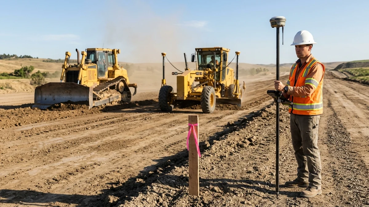
Field teams running machine control grading rely on verified surface models, localized survey control, daily benchmark verification shots, and cutting-edge wear checks to keep earthmoving blades on design grade. Coordinate these grading workflows with the sitework, earthmoving and drainage hub, the smart jobsite technology hub, and the Proctor compaction test guide.
Under Michigan Department of Transportation automated machine guidance special provisions, Automated machine guidance (AMG) is the process of automatically adjusting the motion of a machine with an onboard computer that obtains its position from global positioning systems, robotic total stations, lasers, or combinations of similar methods while referencing the Contractor’s model developed for the project.
Under Caltrans automated machine guidance special provisions, the digital construction model is the three-dimensional model used by the Contractor’s AMG equipment, the digital design model is the three-dimensional model representing the finished grade, and the digital terrain model is the three-dimensional model representing the original ground before job site activities start.
Under Caltrans automated machine guidance special provisions, site calibration or localization is the process that establishes the relationship between the observed control point coordinates and the site coordinate system (usually grid), and the term applies to both GNSS and robotic total station equipment.
| Grading operation or check | Documented source statement |
|---|---|
| Clearing side slopes | In the Michigan Department of Transportation automated machine guidance sample work plan, for clearing stakes, a bulldozer fitted with GPS used to clear brush from roadway side slopes is able to achieve a positional tolerance within 1 ft. |
| Grading roadway slopes and ditches | In the Michigan Department of Transportation automated machine guidance sample work plan, for slope stakes, a bulldozer fitted with GPS used to grade roadway slopes and ditch areas is able to achieve a positional tolerance within 0.10 ft. |
| Grading clay subgrade and placing stone | In the Michigan Department of Transportation automated machine guidance sample work plan, for subgrade stakes and undercut stakes, a bulldozer and wheeled grader fitted with GPS used to grade the roadway to clay grade and place stone are able to achieve a positional tolerance within 0.08 ft. |
| Final stone trimming with total stations | In the Michigan Department of Transportation automated machine guidance sample work plan, after stone is placed and rough graded, a trimming machine guided by total stations used to trim the stone to the final grade is capable of achieving a positional tolerance within 0.02 ft. |
| Daily equipment setup check | Under Caltrans automated machine guidance special provisions, before starting daily work requiring AMG, check testing must be conducted for the proper setup of the GNSS or robotic total station equipment to ensure it achieves accuracies within 0.10 foot in both horizontal and vertical directions for rough grading and 0.05 foot in horizontal directions and 0.02 foot in vertical directions for final grades. |
| Finished subgrade elevation match | Under Wisconsin Department of Transportation construction staking specifications, for AMG construction tolerances, the finished work must vertically match existing or other completed features and conform to revised plan elevations within +/- 0.10 feet for subgrade. |
| Dozer cutting-edge straightness | In the Trimble Earthworks dozer operator's manual, the cutting edge must be replaced if there is more than a 3 mm (1/8 inch) deviation (whether downward bow, upward bow, or end wear) when compared against a flat surface such as concrete or pavement or a string tied across the bottom of the cutting edge. |
TIN surface models, electronic engineering data files, and fleet version control
Preparing three-dimensional machine control earthwork files starts with work plan submittals, model format verification, cross-section overlays, and in-cab file transfer controls.
Under Michigan Department of Transportation automated machine guidance special provisions, the Contractor will notify the Engineer of the intent to use AMG within 10 calendar days of award.
Under Michigan Department of Transportation automated machine guidance special provisions, if AMG will be used, the Contractor must provide an AMG work plan to the Engineer at least 2 weeks prior to the start of AMG operations.
Under Michigan Department of Transportation automated machine guidance special provisions, the AMG work plan must identify the Contractor’s past experience with AMG operations, model revision procedure(s), description of AMG equipment, equipment calibration procedures, equipment calibration frequency, and a description of the control necessary to support the proposed AMG operation(s).
Under the South Carolina Department of Transportation design-build automated machine guidance supplemental specification (Section 105.8 AMG-DB), at least 30 days prior to using AMG, the Contractor must submit to the RCE a written AMG work plan that includes a description of the manufacturer, model, and control software version of the AMG equipment and project site calibration procedures, including equipment calibration and calibration frequency.
Under Caltrans automated machine guidance special provisions, the Contractor must submit an AMG QC plan at least 15 days before starting work requiring AMG.
Under Caltrans automated machine guidance special provisions, Electronic data file control in the AMG QC plan must include the name and contact information of the person responsible for the electronic files, the DCM file-naming convention, a description of the process that will be used to upload the DCM to the AMG equipment, and a description of the process that will be used whenever updated DCM files are required to be uploaded to the AMG equipment.
Under Wisconsin Department of Transportation construction staking specifications, the contractor must submit a comprehensive written AMG work plan for department review at least 5 business days before the preconstruction conference, designating which portions of the contract will be done using AMG versus conventional staking, designating a single staff person as the primary contact for AMG technology issues, and listing and mapping the primary and secondary control points enveloping the site.
In the Minnesota Department of Transportation automated machine guidance inspector’s job guide, the Inspector must document that the Contractor and Engineer agree on the in-place surface model(s) and AMG bottom of muck excavation surface model(s) to use during AMG excavation efforts (which constitute the model of record), and document the file name(s) and date and time stamps associated with the model of record.
Model file formats, cross-section verification, and revision tracking
Under Michigan Department of Transportation automated machine guidance special provisions, the Contractor must provide the model or phased model to the Engineer at least 10 calendar days prior to the start of any AMG operations by submitting 3D Line String Models in Drawing Exchange Format (DXF) and Triangle Models in an Extensible Markup Language (XML).
Under the South Carolina Department of Transportation design-build automated machine guidance supplemental specification (Section 105.8 AMG-DB), Electronic engineering data files for AMG include Horizontal Alignments in LandXML format, Vertical Alignments in LandXML format, 3D surface model DTM files in LandXML format for finish grade, and 2D or 3D break lines in DGN or DXF format for finish grade.
Under the South Carolina Department of Transportation design-build automated machine guidance supplemental specification (Section 105.8 AMG-DB), if proposed cross sections were not created from the 3D AMG model, the Contractor must generate red-line cross sections from the 3D AMG model at a minimum of 50 feet interval and overlay to the proposed design cross sections, and if the 3D AMG Model is revised during construction, submit the revised Model to the RCE with a detailed narrative outlining any changes made to the Model.
Under Caltrans automated machine guidance special provisions, the Contractor must create the digital construction model (DCM), convert the electronic design files to a format compatible with the AMG system at the Contractor’s own risk, and submit copies of the digital construction model files and any updates to them in LandXML format.
Under Michigan Department of Transportation automated machine guidance special provisions, Electronic Model Revision includes compensation for revisions to the Contractor’s model and will be paid for at a fixed unit price of $150.00 per hour.
In-cab file synchronization, USB formatting, and surface selection
In the Trimble Earthworks dozer operator’s manual, when automatic file sync is enabled in the Web Interface, files automatically synchronize to Connected Community every 15 minutes whenever the machine is powered and has an active internet connection, and the operator is not told when the sync is in progress or if it was successful.
In the Trimble Earthworks dozer operator’s manual, the TD520 display only supports USB flash drives that are FAT32 format, and any USB flash drive larger than 32GB may require a third-party application to format it as FAT32.
In the Trimble Earthworks dozer operator’s manual, when transferring files from an external storage device to the machine, all files on the machine that have the same name as the files on the external storage device will be overwritten with the external storage device files, including the user preferences file userdata.pref.xml.
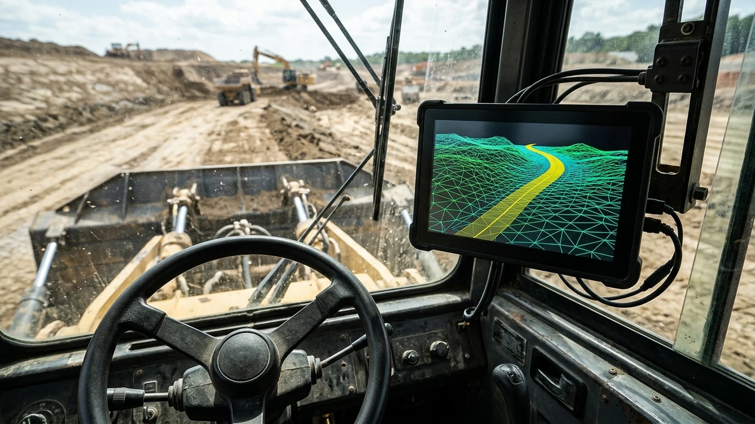
Site calibration, control point spacing, and daily benchmark shots
Executing a site calibration benchmark check ties satellite and total-station observations to the project coordinate system before daily production starts.
In Trimble Siteworks site calibration guidance, the project calibration is stored in a DC file and can also be exported as a CFG file for use with Trimble GS900 or as a CAL file for use with Trimble Earthworks machine control systems, and the software notifies the user after three points have been measured whether the calibration is in or out of tolerance.
In Trimble Siteworks site calibration guidance, the danger of using residuals as the only means of controlling a calibration is that the best precisions can be achieved using the wrong combination of points in the calibration solution, and when an inclined plane is in use, this manipulation of residuals can result in a steeper tilt of the plane to best fit the data, resulting in better precisions and an in-tolerance calibration. In Trimble Siteworks site calibration guidance, monitor the tilt of the plane closely, especially when the geometry of the control points is not strong. In Trimble Siteworks site calibration guidance, widespread control that covers the entire site is good; narrow-based control around a corridor is not as good. In Trimble Siteworks site calibration guidance, an incorrect tilt of the plane can result in increasing errors in height as you move away from the center of the controlled area.
Survey control spacing and localization submittals
Under Michigan Department of Transportation automated machine guidance special provisions, Initial AMG control information (Point, Northing, Easting, Elevation, and Description) must be submitted to the Engineer at least 2 calendar days prior to AMG operations.
Under Michigan Department of Transportation automated machine guidance special provisions, the Contractor must provide and maintain one set of stakes denoting control points and every 200 feet with the station and offset clearly labeled for each roadway alignment.
In the Michigan Department of Transportation automated machine guidance sample work plan, additional AMG control set to guide the trimmer and paver is set at a spacing of 500 ft in an alternating pattern throughout the project, with vertical accuracy within 0.02 ft accomplished by differential leveling procedures.
Under the South Carolina Department of Transportation design-build automated machine guidance supplemental specification (Section 105.8 AMG-DB), at minimum, secondary control points for AMG operations must be established along the length of the project at intervals not to exceed 1000 feet, with elevations established using differential or trigonometric leveling from the project benchmarks.
Under the South Carolina Department of Transportation design-build automated machine guidance supplemental specification (Section 105.8 AMG-DB), the Contractor must provide a clearly marked station stake at a minimum of every 500 feet on an offset from the edge of pavement as specified by the RCE.
Under Caltrans automated machine guidance special provisions, the Department sets control points to a minimum of 0.07 foot local horizontal accuracy and 3rd order vertical accuracy standards, setting 6 survey control points or 2 per mile, whichever is greater, for slope stakes and rough grade stakes.
Under Caltrans automated machine guidance special provisions, the Contractor must perform GNSS site calibration or localization to the survey control points at least 5 business days before starting work requiring AMG, check each survey control point for accuracy, and submit the GNSS site calibration or localization results within 1 business day of testing, allowing 3 business days for review.
Under Wisconsin Department of Transportation construction staking specifications, for conventional subgrade staking, construction stakes or marks are set at intervals of 100 feet or more frequently for rural sections and at intervals of 50 feet or more frequently for urban sections, locating stakes to within 0.25 feet horizontally and establishing the grade elevation to within 0.03 feet vertically.
Common GNSS error sources, sensor initialization, and fixed control point blade checks
In Trimble Siteworks site calibration guidance, the most common sources of error when using RTK GNSS systems are a poor project calibration, incorrect base antenna height, incorrect rover antenna height, incorrect selection of the correct antenna type at the base or rover (which causes height errors), incorrect location of the base station antenna, and a GNSS rod bubble that is out of adjustment or a bent rod; after starting the rover each day, the software prompts the user to recheck the system setup and logs all recheck operations.
In the Trimble motor grader grade control operator’s manual, if a machine without a pitch or mainfall sensor is moved more than 10 m (33 ft) with the system turned off, when the system starts up it discards the old pitch information and displays the Low Accuracy (Move) flashing warning message until the machine is moved in a straight line for a few meters.
In the Trimble motor grader grade control operator’s manual, any movement of the cutting edge when the machine is stationary causes errors in the estimated orientation and pitch of the machine that remain until the machine is moved with the cutting edge in a fixed position; when benching a 3D sensor with sideshift, you can only bench for Elevation (not Eastings and Northings), and when checking 3D guidance using a control point, you must place the focus tip at the control point without moving the cutting edge.
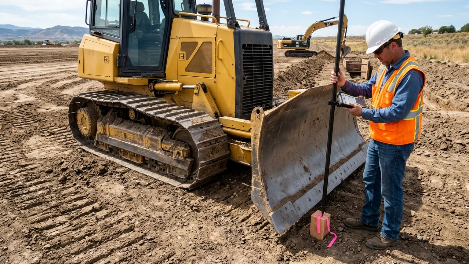
In the Trimble motor grader grade control operator’s manual, the maximum operating extension for an electric mast carrying a GNSS receiver is 0.6 m (2 ft).
In the Trimble motor grader grade control operator’s manual, the maximum operating extension for an electric mast carrying a UTS target is 0.9 m (3 ft), and by convention target IDs of 9 through 16 are used for machine control applications while IDs of 1 through 8 are reserved for surveying applications.
In the Michigan Department of Transportation automated machine guidance sample work plan, the total stations used to guide the AMG trimming machine and concrete paver are sent in for cleaning and calibrating every year, and a check and adjust program is performed on each total station once a month to ensure proper function.
Independent quality assurance, curve checks, excavation verification, and milling hold points
Under Michigan Department of Transportation automated machine guidance special provisions, the Engineer will perform continuous and independent quality assurance for AMG operations to ensure compliance of the finished surfaces and is prohibited from using the Contractor’s equipment in the quality assurance verification process.
Under Caltrans special provisions section 5-1.26 Grade Quality Control (for projects with more than 5,000 cubic yards of earthwork construction), the frequency of grade checking of a roadway must be increased wherever its curve radius is 500 feet or less, in areas of a superelevation transition, and at intersections.
In the Minnesota Department of Transportation automated machine guidance inspector’s job guide, to verify AMG excavation system calibrations, the Inspector uses a rover or robotic total station to verify a minimum of 10 locations that are at least 2 feet apart using varying bucket orientations, moving the cutting edge of the excavation equipment to the measurement location without pre-marking and marking the verification location on the recorded cutting edge location (left, center, or right edge) after the cutting edge is placed on the natural ground.
In the Minnesota Department of Transportation automated machine guidance inspector’s job guide, A hold point for AMG milling using a relative surface occurs if 5 percent or more of the milling depths in the Contractor’s AMT-203 form exceed the tolerance of plus or minus 0.03 feet for a given daily report, or if 50 percent or more independent verification measurements completed by the Engineer exceed plus or minus 0.03 feet over 1,000 continuous linear feet (where measurements are collected at a linear increment of 100 feet or less).
In the Minnesota Department of Transportation automated machine guidance inspector’s job guide, A hold point for AMG milling using Robotic Total Stations occurs if 5 percent or more of the milling depths in the Contractor’s AMT-203 form exceed the tolerance of plus or minus 0.02 feet for a given daily report, or if 50 percent or more independent verification measurements completed by the Engineer exceed plus or minus 0.02 feet over 1,000 continuous linear feet (where measurements are collected at a linear increment of 100 feet or less).
GPS grader and dozer blade wear checks, straightness limits, and trim practices
Performing a gps grader blade wear check and verifying dozer cutting-edge geometry prevents worn steel edges from introducing vertical grade offsets.
In the Trimble motor grader grade control operator’s manual, calibration settings for AS400 and RS400 sensors are not saved in a machine settings file and are not restored when you restore the settings file.
In the Trimble motor grader grade control operator’s manual, Cab-mounted GNSS systems will fail to record deviations in cut/fill less than 0.3 m (about 1 ft) when the lightbar or on-grade tolerance is set to the default value.
In the Trimble Earthworks dozer operator’s manual, on Cat D7 machines, the operator should check the Hours since last Body Sensor Check on the System Status page and notify a technician when the operating hours get close to 1000.
Measuring cutting-edge wear and updating blade manager values
In the Trimble motor grader grade control operator’s manual, to check and set blade wear compensation, measure the cutting edge height to the center of the bolt holes and edit the Cutting edge height field in the Blade Wear dialog; if the blade wears unevenly, use an average value, noting that guidance will never be better than the range of the differences in cutting edge height.
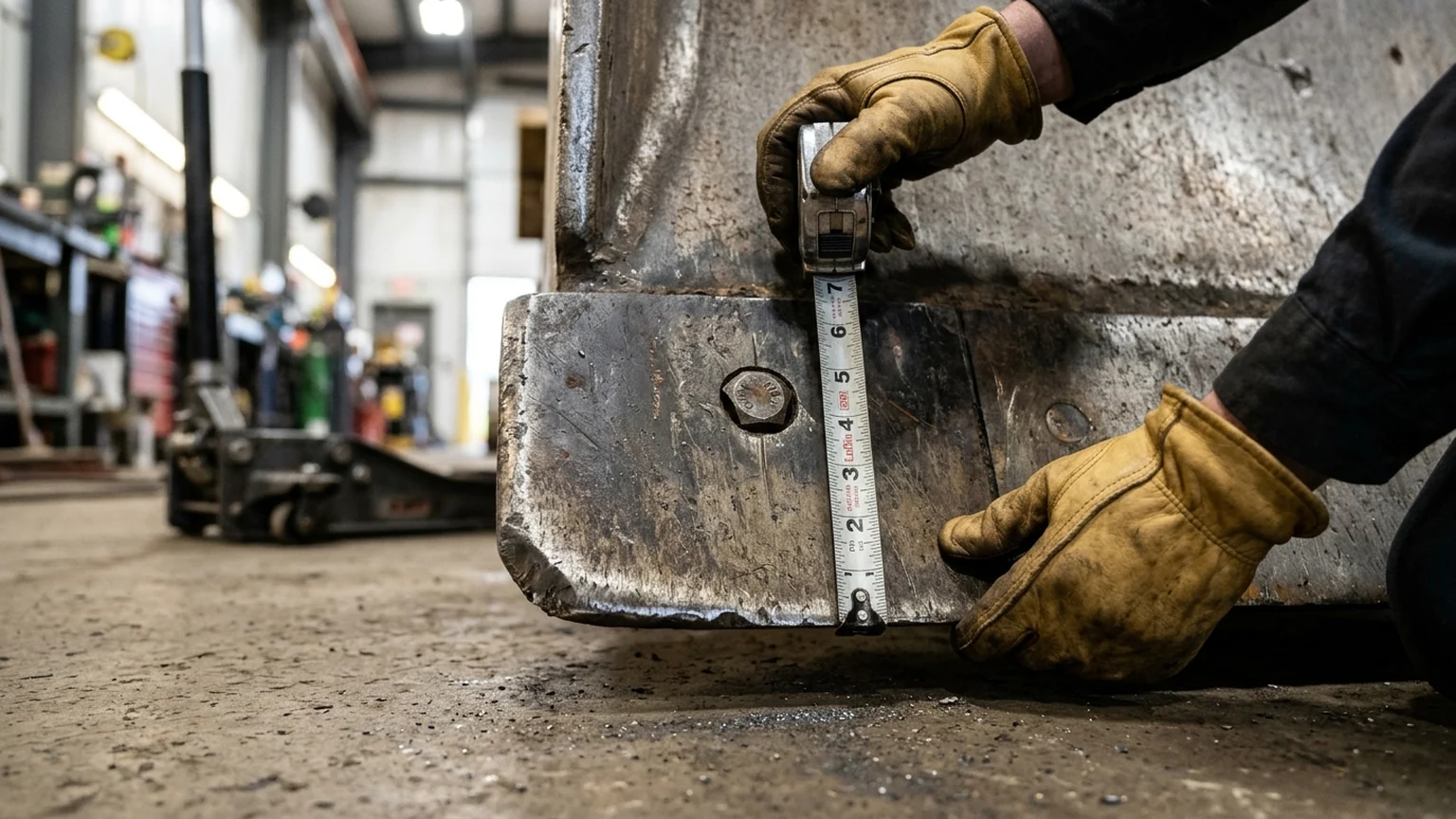
In the ABTECH dozer cutting-edge calibration procedure, after adjusting the blade wear value, position the center of the blade over a known reference point with the blade level with the tracks and slope at 0%, adjust the Height Reference to the center of the blade, and compare the Height Tool Point Position to the known position of the control point.
In the Trimble Earthworks dozer operator’s manual, when Overcut Protection is on and vertical guidance other than 2 Points is selected, the entire length of the cutting edge is checked against the design surface, whereas when 2 Points vertical guidance is selected, only the tips of the cutting edge are checked against the design surface.
In the Trimble Earthworks dozer operator’s manual, to edit the cutting edge length, update the A and B values in the Cutting Edge Length screen, accessed via the Edit button on the Blade Manager screen.
Valve speed diagnostics, blade load, final trim pass, and compaction handoff
In the Trimble motor grader grade control operator’s manual, during an automatic-control test pass, if the cut surface shows long period waves (wave lengths greater than about 2 m or 6 ft), the valve speed may be too low, whereas if the cut surface shows the blade is jittery, the valve speed may be too high.
In the Trimble Earthworks dozer operator’s manual, keeping the blade load between one-quarter and one-half full during the run ensures optimum performance, because an overloaded blade reduces response and spills material out the sides while an empty blade has no dampening from the material and is more likely to chatter.
In the Trimble Earthworks dozer operator’s manual, on machines with a rotating blade, moving the tip of the blade back at least 150 mm (6 inches) increases the stability of the dozer and improves surface smoothness over a square blade, and a final pass of 10 mm (1/2 inch) using an angled blade is recommended to cut down to the final height.
Once trimming reaches design elevation, field crews verify lift density against laboratory compaction references covered in our Proctor compaction test guide.
Standard Proctor (ASTM D698) uses a laboratory compaction effort of 12,400 ft-lbf/ft3, whereas Modified Proctor (ASTM D1557) uses a laboratory compaction effort of 56,000 ft-lbf/ft3.
Daily pre-shift verification worksheet and field questions
Use the daily verification schedule below alongside the project control log, and return to the sitework, earthmoving and drainage hub or the smart jobsite technology hub when coordinating corridor handoffs.
| Daily check stage | Verification requirement |
|---|---|
| Cutting-surface and rover comparison | In the Michigan Department of Transportation automated machine guidance sample work plan, A site calibration is performed prior to the start of the project and loaded into the machines, daily checks are made between the cutting surfaces of the AMG equipment and an independent GPS rover, and AMG equipment is constantly monitored and adjusted for common wear and hydraulic performance. |
| Start-of-day check and recalibration | Under the South Carolina Department of Transportation design-build automated machine guidance supplemental specification (Section 105.8 AMG-DB), at minimum, the Contractor must check, and if necessary, recalibrate the AMG system at the beginning of each work day and any time the results are suspected of being out of conformance with the specifications, and provide calibration results and out of tolerance checks to the RCE. |
| Daily production check submittal | Under Caltrans automated machine guidance special provisions, before starting daily production, the Contractor must conduct check testing of the AMG equipment and the GNSS rovers and submit the check-testing results as informational submittals within 1 business day after check testing. |
| Random station cross-section checks | Under Wisconsin Department of Transportation construction staking specifications, the contractor must check the work against the plan elevation at randomly selected points on cross-sections located at stations evenly divisible by 100 at the approved frequency and submit the results of these random checks to the engineer daily. |
Why is a multi-point calibration preferred over a two-point calibration?
In Trimble Siteworks site calibration guidance, Trimble recommends using a multi-point calibration of at least three points wherever possible; in a two-point calibration, the first point establishes the position and elevation for the project, the second point establishes the project orientation, and heights for the project are computed using a simple block shift method that ties all heights to the first measured control point.
Which dozer blades require raising and lowering at startup for sensor initialization?
In the Trimble Earthworks dozer field reference guide, when starting Earthworks, 6 way blades require raising and lowering the blade for sensor initialization, whereas push blades do not.
Why must blade wear be checked after restoring a machine settings file?
In the Trimble motor grader grade control operator’s manual, when you restore a machine settings file, a dialog warns you to always check the Blade Wear dialog because the machine cutting edge may have worn or been renewed since the machine settings were saved.
Sources
- Michigan Department of Transportation (MDOT) — Automated Machine Guidance Special Provision
- Michigan Department of Transportation (MDOT) — Automated Machine Guidance Sample Work Plan
- South Carolina Department of Transportation (SCDOT) — Section 105.8 Automated Machine Guidance supplemental specification for design-build projects (AMG-DB).
- California Department of Transportation (Caltrans) — Special provisions for State Route 10 in Riverside County, including automated machine guidance sections 5-1.24B and 5-1.25.
- Wisconsin Department of Transportation (WisDOT) — Construction Staking Specifications
- Minnesota Department of Transportation (MnDOT) — Inspector’s Job Guide: Automated Machine Guidance
- Trimble Inc. — Trimble Siteworks Help: Calibrating the Site
- Trimble Inc. — Grade Control System for Motor Graders Operator’s Manual
- Trimble Inc. — Trimble Earthworks Dozer Operator’s Manual
- Trimble Inc. / SITECH Southwest — Earthworks Dozer Field Reference Guide
- ABTECH Knowledge Base — Adjusting Blade Wear / Calibrating a Dozer Cutting Edge
- SmartSite Construction — Proctor Compaction Test: Standard vs. Modified and Optimum Moisture
Explore the related topic and technical references.