Riprap Erosion Control: Stone and Filter
Riprap is large angular stone that armors soil in concentrated flow. Size it to shear or to velocity and depth, keep the slope limit, and place a filter underneath.
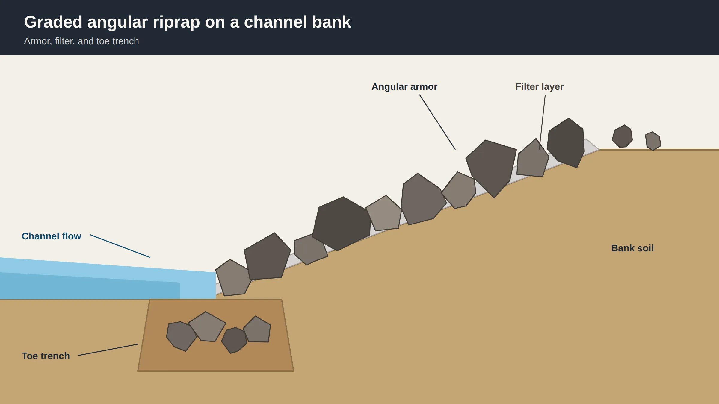
Riprap is a layer of large stones that protects soil from erosion in areas of high or concentrated flows. On a construction site the stone should be field stone or quarry stone that is angular and variably sized. Size follows the shear of the flow, or, for a bank revetment, a velocity-and-depth method. A filter goes down before the rock so the soil does not move through the stone.
The Minnesota Stormwater Manual describes riprap as a permanent layer of large, angular stone, cobbles, or boulders that armors soil against erosion and scour in concentrated flow or wave energy. Wikipedia describes the same family of work as human-placed rock or other hard, heavy, unconsolidated material used to protect shoreline structures against scour and water, wave, or ice erosion. EPA notes that the practice is especially useful for armoring channel and ditch banks. Place that work in the broader sitework, earthmoving, and drainage sequence, next to the grades and outlets the stone has to live with.
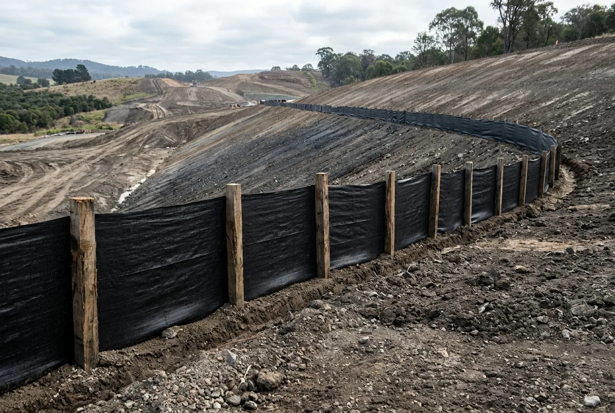
A silt fence is a temporary vertical permeable interceptor for overland, non-concentrated sheet flow. The trench, post, and overlap rules for that barrier stay on the silt fence guide. Riprap is the permanent armor once flow is already concentrated.
Is riprap effective on a channel or slope?
Proper design and installation of riprap can reduce flow velocities and prevent erosion of the protected area. Improper use of riprap can increase erosion. Rock placed several particles thick can adjust to a local displacement without a complete failure. HEC-23 calls that behavior self-healing.
A revetment does not provide resistance against geotechnical instability, such as slumping failure in saturated streambanks and embankments. Revetments are also relatively unsuccessful in stabilizing streambanks and streambeds in degrading streams. Those two limits sit outside the stone-size calculation. The bank mass and the channel’s long-term degradation still need their own check.
What are the downsides of loose riprap?
Loose riprap fails in more than one way, and each manual states its own slope limit. Keep the face slope, the geotextile slope, and the channel gradient on the sentence that belongs to that manual.
For slopes steeper than 2:1, EPA says developers should consider using materials other than riprap for erosion protection. Slopes greater than 2:1 can cause riprap loss due to erosion and sliding.
For riprap installations, the maximum recommended face slope in HEC-11 is 1V:2H. HEC-15 says channels lined with gravel or riprap on side slopes steeper than 1:3 may become unstable and should be avoided where feasible. Round stones are acceptable as riprap in HEC-15 provided they are not placed on side slopes steeper than 1:3 (V:H). HEC-11 allows round material provided it is not placed on slopes greater than 1V:3H.
The Minnesota Stormwater Manual says geotextile should not be used on slopes exceeding 2:1 horizontal to vertical. Fully grouted riprap is not allowed in Minnesota public waters.
Channel gradient is a different number from the face slope. HEC-15 recommends equation 6.11 when channel slope is greater than 10 percent, and equation 6.8 for slopes less than 5 percent. Between 5 percent and 10 percent, apply both and use the larger size. On a steep slope the weight of a stone has a significant component in the direction of flow, so the same discharge needs larger stones than on a milder gradient. The USACE method in NRCS Technical Supplement 14C is for channels with a slope of 2 percent or less and Froude numbers less than 1.2.
HEC-11 names four classic failure modes: particle erosion, translational slide, modified slump, and slump. The riprap design guidelines in that circular apply to particle erosion only. Particle erosion is the most common erosion mechanism. It results when the tractive force exerted by the flowing water exceeds the bank material’s ability to resist movement. Probable causes include stone that is not large enough, individual stones removed by impact or abrasion, a side slope so steep that the angle of repose is easily exceeded, and a gradation that is too uniform.
Translational slides usually start when the channel bed scours and undermines the toe of the riprap blanket. Probable causes are a bank side slope that is too steep, excess hydrostatic pore pressure, and loss of foundation support at the toe. Undermining of revetment toe protection is one of the primary mechanisms of riprap revetment failure. Slump is a rotational-gravitational movement of material along a surface of rupture that has a concave upward curve.
HEC-23 lists a major shortcoming of riprap design techniques: the assumption that revetment failures are due only to particle erosion. Listed reasons for failure include a particle size that was too small because shear stress was underestimated or velocity was underestimated, a missing or damaged filter blanket, side slopes that were too steep, improper gradation, and improper placement. Winnowing failure, in the pier-riprap experiments, is removal of the underlying finer bed material through voids in the riprap.
When the stone is held in a wire enclosure, EPA says this practice is typically referred to as a gabion. A wire basket is a different system from a loose stone blanket.
What goes under riprap stone?
Three manuals describe the layer under the stone in three different ways. Keep the wording with the manual.
EPA says to apply a filter fabric, geotextile material, or a layer of gravel before applying the riprap, so the underlying soil does not move through the rock. The Minnesota Stormwater Manual says riprap should always be underlain by granular filter material or a nonwoven geotextile so the underlying soil does not pipe through the stone. If that filter material is not used, the rock will become buried in the soil on which it was placed. HEC-15 says that when rock riprap is used, the underlying filter may be either a granular filter blanket or a geotextile fabric. Wikipedia says a filter is installed where necessary. HEC-11 defines a filter as a transitional layer of gravel, small stone, or fabric placed between the underlying soil and the structure. It prevents migration of the fine soil particles through voids in the structure.
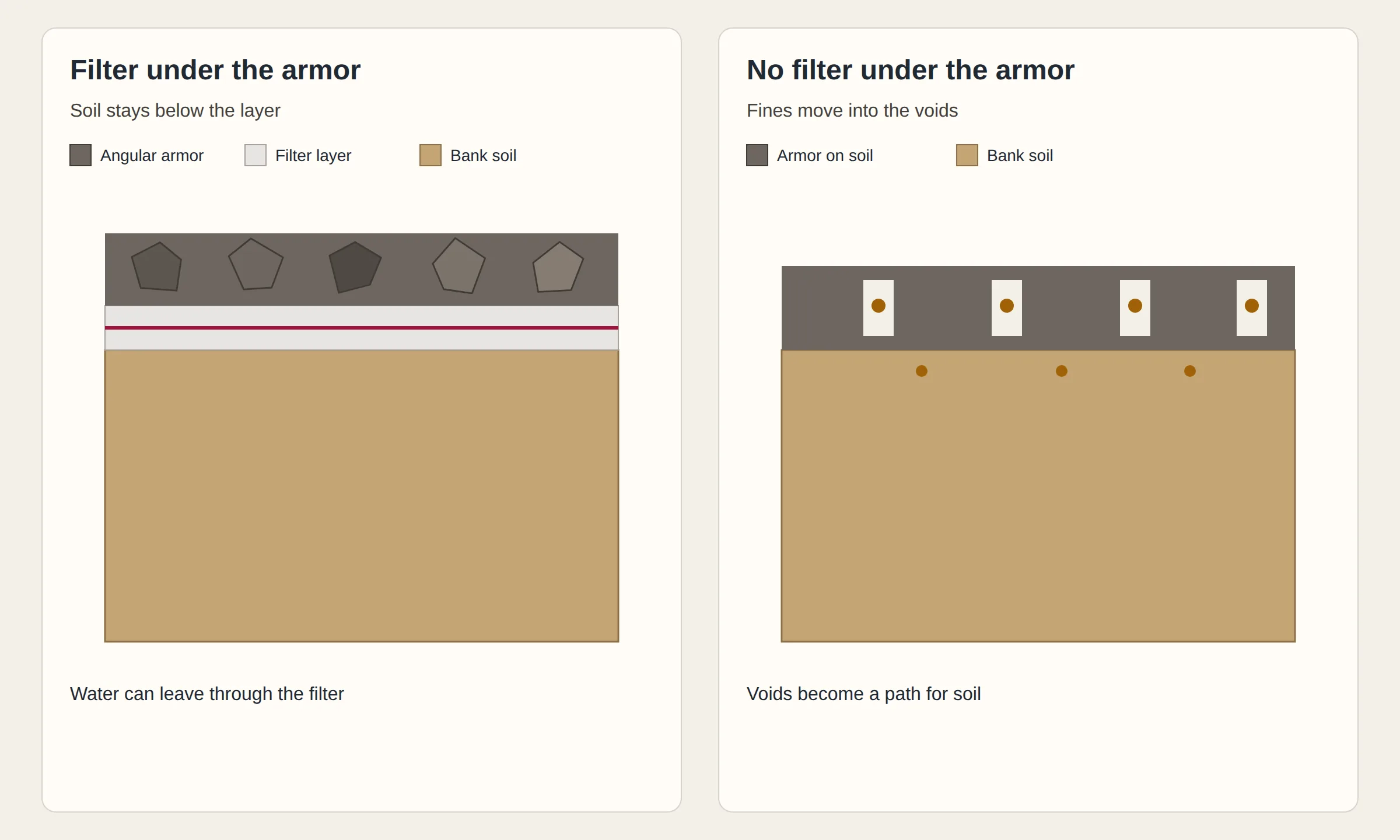
If filter openings are too large, piping can erode the bank material. If openings are too small, hydrostatic pressure behind the filter can form a slip plane and a translational slide. A filter ratio of 5 or less between layers will usually be stable. The ratio is D15 of the coarser layer to D85 of the finer layer. Not more than 5 percent of the filter material should pass the No. 200 sieve. HEC-23 calls filter design the most overlooked aspect of revetment riprap design. A correct filter limits the loss of fines and keeps a permeable interface.
The hydraulic conductivity of the filter should never be less than the material below it. For these countermeasure installations, HEC-23 says the hydraulic conductivity of the filter should be at least 10 times the hydraulic conductivity of the underlying material.
HEC-15 says the minimum thickness for a granular filter blanket should not be less than 150 mm (6 in). HEC-11 says a single filter layer should range from 150 mm to 380 mm, and each layer of a multiple-layer blanket from 100 mm to 200 mm. HEC-23 says a granular stone filter should be at least 4 times the d50 of the filter stone or 6 inches, whichever is greater, and 50 percent thicker when placed under water. A practical minimum in the same guidance is 6 to 8 inches, increased by 50 percent for placement under water.
Judge a geotextile filter for soil retention, permeability, clogging, and survivability. Problematic soils named for that check include non-cohesive silts, gap graded soils, alternating sand/silt laminated soils, dispersive clays, and rock flour. The Minnesota Stormwater Manual says to overlap geotextile edges by at least a foot and a half in the downhill or downstream direction. The same manual’s geotextile table lists a minimum permittivity of 0.5. Selecting the drainage geotextile that must retain the surrounding soil while allowing water to enter the drainage aggregate is a different job, covered in the woven and nonwoven drainage fabric guide.
How does angular riprap resist scour?
Angular field or quarry stone is the EPA material. Most igneous stones, such as granite, have suitable durability, and the stone should resist cracking during freeze and thaw cycles. Do not use crushed concrete for riprap. That prohibition is the construction-site fact sheet. HEC-11, a different circular, says broken concrete must be adequately broken or fragmented before it is acceptable as riprap in that circular.
HEC-15 says riprap constructed with angular stones has the best performance. HEC-11 says the same for angular material. HEC-23 prefers stones tending toward subangular to angular because the particles interlock more than rounded particles of the same weight. Flat slab-like stones should be avoided since they are easily dislodged by the flow. An approximate shape guide in HEC-11 is that neither the breadth nor the thickness of a single stone should be less than one-third its length. The maximum allowable shape factor A/C in HEC-23 is 3.0, with A the length and C the thickness. The Minnesota Stormwater Manual, citing its stone specification, says each individual stone has at least one fractured face, and that riprap and the granular filter are 100 percent virgin materials.

Use a well-graded mixture of rock sizes instead of one uniform size. The Minnesota Stormwater Manual says well-graded riprap, rather than uniform riprap, forms a dense, flexible cover that can adapt on uneven surfaces. HEC-15 treats a gradation with D100/D50 and D50/D20 between 3.0 and 1.5 as the usual acceptable band. HEC-23 sets a target uniformity ratio d85/d15 of 2.0, with an allowable range of 1.5 to 2.5. With the recommended gradations in that guideline, d50 equals 1.20 times d30.
How do you size riprap stone?
Riprap size depends on the shear stress of the flows. Median stone diameters range from 9.5 to 23 inches, with no stones larger than 34 inches. Read that EPA band as the reported median-diameter range. The channel-lining shear equation and the Minnesota maximum-rock-size table are separate tools, and each one is stated below with its own manual.
Permissible shear stress for riprap and gravel linings is given by an equation in mean riprap size D50, the specific weight of the stone, the specific weight of the water, and a dimensionless Shields parameter. A specific weight of stone of 25,900 N/m3 (165 lb/ft3) is the typical value, and a different available stone should use the site-specific value. For many roadside channel applications, when the Reynolds number is less than 4x10⁴, a Shields parameter of 0.047 should be used. The safety factor should also increase with Reynolds number, and it should not be decreased below the values in Table 6.1.
The recommended bank-revetment sizing method in HEC-23 is the Maynord procedure published as USACE Engineering Manual 1110-2-1601, and it uses velocity and depth as its primary design parameters. The recommended safety factor for bank revetment is 1.1. Specific gravity of the riprap in this equation is usually taken as 2.65. A minimum allowable specific gravity of 2.5 is required for riprap applications. The NRCS supplement limits that USACE method to a channel slope of 2 percent or less and a Froude number less than 1.2. The Isbash formula, from 1936, was developed for depositing rocks into moving water, and the Isbash curve should only be used for quick estimates or comparisons. Its coefficient C is 0.86 for high turbulence and 1.20 for low turbulence.
The Minnesota Stormwater Manual velocity table lists a maximum rock size of 6 inches at 5.0 feet per second, 12 inches at 8.5, 18 inches at 10, 24 inches at 12, and 36 inches at 15. Read that column as a maximum rock size at the stated velocity.
Lining thickness is its own measurement, taken normal to the ground surface. HEC-15 says the thickness should equal the diameter of the largest rock, which for most gradations is 1.5 to 3.0 times the mean riprap diameter. HEC-11 says layer thickness should not be less than the spherical diameter of the D100 stone, or less than 1.5 times the spherical diameter of the D50 stone, whichever is greater. It should not be less than 300 mm for practical placement. HEC-23 says layer thickness should not be less than 1 ft (0.30 m) for practical placement. Increase the layer thickness by 50 percent when the riprap is placed underwater.
At the break between a steep slope and a culvert entrance, HEC-15 says the riprap layer thickness should equal three to five times the mean rock diameter, with the top of the layer flush with the culvert invert. Use that three-to-five-diameter thickness at the culvert break. Use the largest-rock thickness on an ordinary bank lining. For steep channels, freeboard should equal the mean depth of flow, since wave height will reach approximately twice the mean depth.
In the HEC-15 side-slope example, the angle of repose is 38 degrees, Z is 3, the side-slope angle is 18.4 degrees, K2 is 0.86, and the side-slope D50 is 0.137 m against a bottom requirement of 0.135 m. Those inputs belong to that example.
How do you install riprap on a bank?
Grade the bank so the surface does not deviate from the specified slope line by more than 150 mm. Measure the lining thickness normal to that surface. Place the filter, then the armor. Place riprap so it extends up to the maximum flow depth, or to a point where the land surface is stable or vegetation will be satisfactory to control erosion.
The toe material should be placed in a toe trench along the entire length of the riprap blanket. Observed rock toes launch to a final slope of approximately 1V:2H. The volume of rock required for the toe must equal or exceed one and one-half times the volume of rock required to extend the blanket, at design thickness and on a 1V:2H slope, to the anticipated depth of scour. If the toe of the slope is eroding and bioengineering alone cannot control it, lining the toe with stone may be a solution.
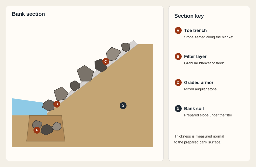
Hand placement produces the best riprap revetment, and it is the most expensive method except when labor is unusually cheap. Placement by dumping and spreading is the least desirable method because segregation and breakage can occur. Dropping stone from a height greater than 0.61 m can rupture filter fabric. Greater drop heights are allowable under water.
What drives riprap placement cost?
The cost of riprap varies depending on location, material type, maintenance frequency, and installation method. Hand placement is the most expensive method except when labor is unusually cheap. Underwater placement uses the thicker armor layer and the thicker granular filter from the sizing rules above, so the quantity placed changes with the method.
Acceptance checklist for stone, toe, and filter
Confirm the stone, the toe, and the filter before the blanket is accepted, then walk it again after high water.
| Check | Accept when |
|---|---|
| Stone size and shape | The median size follows the shear method or the velocity-and-depth method used on the drawing, the mixture is well graded, the particles are angular, and crushed concrete is not used on an EPA construction-site blanket. |
| Toe trench | Toe material sits in a trench along the entire length of the blanket, the launch is about 1V:2H, and the toe-rock volume is at least one and one-half times the rock needed to carry design thickness on a 1V:2H slope down to the anticipated scour depth. |
| Filter | A granular filter or a geotextile is in place before the rock, openings are checked both ways, and fabric was not dropped from more than 0.61 m in the dry. |
| After flow | Inspect riprap annually and after major storms, and after high flows, and repair damaged riprap or geotextile promptly. |
EPA says to inspect riprap areas annually and after major storms. If storms damage the riprap or geotextile material, repair it promptly to prevent a progressive failure. The Minnesota Stormwater Manual says to inspect riprap after high flows so deficiencies are corrected early.
Sources
- U.S. EPA stormwater riprap fact sheet
- FHWA channel lining manual
- FHWA metric bank protection circular
- FHWA bridge scour countermeasures, design volume
- FHWA bridge scour countermeasures, guideline volume
- USDA stream restoration supplement on stone sizing
- Wikipedia article on riprap
The Minnesota Stormwater Manual, erosion prevention practices for riprap, is cited by name in the sections above.
Explore the related topic and technical references.